Belt-type sintering machine material layer steam jetting humidifying device and humidifying method

A humidification device and sintering material technology, applied in the direction of combustion methods, lighting and heating equipment, combustion equipment, etc., can solve the problems of slowing down the vertical sintering speed and reducing the running speed of the sintering machine, so as to reduce the solid fuel consumption and sintered solids Effects such as fuel consumption and CO2 reduction

Inactive Publication Date: 2018-08-28
SHANDONG IRON & STEEL CO LTD
View PDF4 Cites 13 Cited by
  • Summary
  • Abstract
  • Description
  • Claims
  • Application Information

AI Technical Summary

Problems solved by technology

[0003] However, in order to ensure that the sintering mixture placed on the sintering machine trolley is completely burned through, it is necessary to slow down the vertical sintering speed to ensure that sufficient heat is utilized, and for this reason the operating speed of the sintering machine needs to be reduced

Method used


Image

  • Belt-type sintering machine material layer steam jetting humidifying device and humidifying method

Examples


Embodiment 1

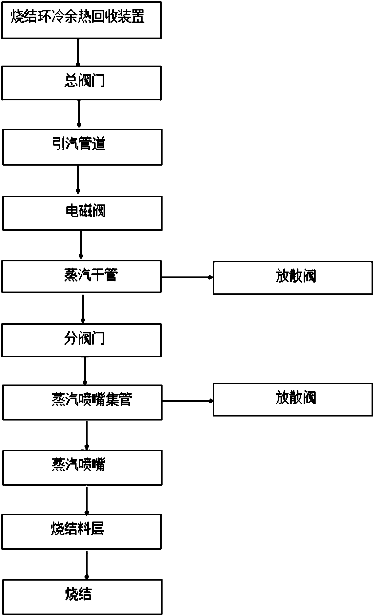
[0036] The steam is introduced from the sintering ring cold waste heat recovery system to the steam main pipe by the steam induction pipe. The steam working condition is 150°C and 0.3MPa. The steam injection nozzle header is set up at a distance of 1 / 3 from the sintering head, and the distance is 5 meters. Add a set of nozzle headers to a quarter of the distance from the tail of the sintering machine. The steam is sprayed vertically on the sintering material layer from the steam injection nozzle. Under the action of the exhaust fan, the steam participates in the sintering reaction, and the sintering area per square meter needs 3.4kg / h amount of steam.

Embodiment 2

[0038] The steam is introduced from the sintering ring cold waste heat recovery system to the steam main pipe by the steam induction pipe. The steam working condition is 150°C and 0.3MPa. The steam injection nozzle header is set up at a distance of 1 / 3 from the sintering head, and the distance is 5 meters. A set of nozzle headers is added to the quarter of the tail of the sintering machine, and the steam is sprayed vertically on the sintering material layer from the steam injection nozzle. h steam volume.

Embodiment 3

[0040] The steam is introduced from the sintering ring cold waste heat recovery system to the steam main pipe by the steam induction pipe. The steam working condition is 150°C and 0.3MPa. The steam injection nozzle header is set up at a distance of 1 / 3 from the sintering head, and the distance is 5 meters. A set of nozzle headers is added to the quarter of the tail of the sintering machine. The steam is sprayed vertically on the sintering material layer from the steam injection nozzle. Under the action of the exhaust fan, the water vapor participates in the sintering reaction, and each square sintering area needs 3.8kg / h steam volume.


PUM


Abstract

The invention discloses a belt-type sintering machine material layer steam jetting humidifying device and a humidifying method. The belt-type sintering machine material layer steam jetting humidifyingdevice comprises a steam introducing system and a steam jetting system; the steam introducing system comprises a steam introducing pipeline and steam drying pipes; an inlet of the steam introducing pipeline is connected with a steam source; introduced steam enters the steam drying pipes; the steam drying pipes are arranged at the parts, in the advancing direction of a sintering machine, of the two sides of a sintering machine trolley; the steam jetting system comprises a plurality of nozzle collecting pipes; a plurality of steam nozzles are arranged on the nozzle collecting pipes; and the nozzle collecting pipes are arranged on the steam drying pipes. The heat exchange rate of a sintering material layer is increased obviously, the vertical sintering speed of the sintering is increased, and the utilization coefficient of the sintering machine is further increased; and sintering solid fuels are facilitated being thoroughly burnt, heat generated by burning the sintering solid fuels is increased, the quality stability of sintering ore is ensured, and the guarantee is provided for further reducing the sintering solid fuel consumption.

Description

technical field [0001] The invention relates to a steam-injection humidification sintering technology in a material layer of a belt sintering machine, and belongs to the technical field of sintering production in the iron and steel industry. Background technique [0002] With the significant increase in the consumption of blast furnace sinter, the role of sintering machines in large steel mills is becoming more and more important. Improving the output and quality of sinter plays an important role in reducing the cost of the pre-iron process and increasing the profit of the process in large iron and steel enterprises. It is impossible to easily change the type of raw materials, sintering procedures and equipment parameters currently used in the existing sintering machine. In terms of sintering area and sintering mix Under the condition that the bulk density of the material cannot be changed, the only way to increase the output of the sintering machine is to increase the verti...

Claims


Application Information

Patent Timeline
Patent Type & Authority Applications(China)
IPC IPC(8): F27B21/00F23L7/00
CPCF27B21/00F23L7/005
Inventor 周林罗川秦立国唐凌剑张炯
Owner SHANDONG IRON & STEEL CO LTD
Why Eureka
Try Eureka