Lighting device, display device and near-eye display system

A technology for display equipment and lighting devices, which is used in projection devices, instruments, components of color TVs, etc., can solve the problems of high energy rate and compact size, and achieve the effect of high energy rate and compact structure

Active Publication Date: 2021-08-06
BOE TECH GRP CO LTD
View PDF0 Cites 0 Cited by
  • Summary
  • Abstract
  • Description
  • Claims
  • Application Information

AI Technical Summary

Problems solved by technology

[0004] The purpose of the technical solution of the present invention is to provide a lighting device, a display device and a near-eye display system, which are used to solve the problem that the incident light beam and the outgoing light beam used by the LCOS lighting device in the prior art are separated, and it is impossible to achieve higher energy. The problem of high efficiency and compact size

Method used


Image

  • Lighting device, display device and near-eye display system
  • Lighting device, display device and near-eye display system
  • Lighting device, display device and near-eye display system

Examples


Embodiment Construction

[0037] In order to make the technical problems, technical solutions and advantages to be solved by the present invention clearer, the following will describe in detail with reference to the drawings and specific embodiments.

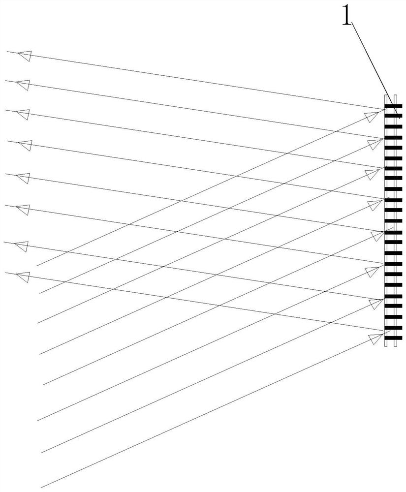
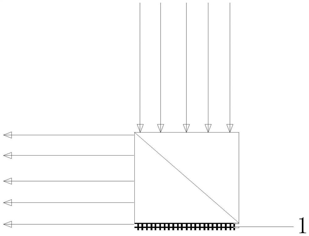
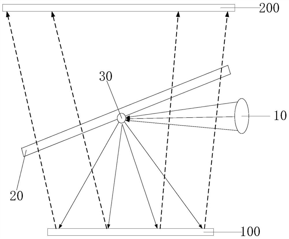
[0038] An embodiment of the present invention provides a lighting device. By setting a light separation module, the light emitted by the light source is transmitted from the light separation module to the light reflection panel in the form of a point lighting source, and the reflected light reflected by the light reflection panel can It is received by the light separation module and transmitted to the beam collection unit. Since the reflected light received by the light separation module is formed into a structure arranged around a point lighting source, the volume of the entire lighting device is mainly composed of the light reflection panel and the light beam collection unit. The area is determined and will not take up too much space, thus ensuring a co...


PUM

PropertyMeasurementUnit
diameteraaaaaaaaaa

Abstract

The invention provides an illuminating device, a display device and a near-eye display system. The lighting device is arranged between the light reflection panel and the light beam collecting unit, wherein the lighting device includes: a light source; a light separation module, the light separation module receives the light emitted by the light source, and forms a A point lighting source arranged opposite to the panel, the point lighting source outputs incident light that can be transmitted to the light reflecting panel, and the light separation module is also used to receive reflected light reflected by the light reflecting panel from the incident light , transmitting the reflected light to the light beam collecting unit; wherein, the reflected light received by the light separation module surrounds the point illumination source. The illuminating device can solve the problem that the incident light beam and the outgoing light beam adopted by the prior art LCOS illuminating device cannot achieve a high energy rate and ensure a compact volume.

Description

technical field [0001] The present invention relates to the field of display technology, in particular to an illuminating device, a display device and a near-eye display system. Background technique [0002] Liquid Crystal on Silicon (LCOS) is a new type of reflective micro liquid crystal display (Micro Liquid Crystal Display, referred to as Micro LCD) projection technology, which uses a complementary metal oxide semiconductor (CMOS) coated with liquid crystal silicon Oxide Semiconductor (referred to as CMOS) integrated circuit chip is used as the substrate of reflective LCD. It is polished by advanced technology and then plated with aluminum as a reflector to form a CMOS substrate. Then, the CMOS substrate is combined with the glass substrate containing transparent electrodes Bonded, and then injected into the liquid crystal package to form an LCOS panel. [0003] At present, reflective liquid crystal on silicon is used in near-eye holographic technology. As a key device i...

Claims


Application Information

Patent Timeline
Patent Type & Authority Patents(China)
IPC IPC(8): G02B27/10G02B27/01
CPCG02B27/0101G02B27/10G02B27/0172G02B27/143H04N9/315G03B21/28G03B21/2073G02F1/136277H04N9/3152
Inventor 石炳川
Owner BOE TECH GRP CO LTD
Why Eureka
Try Eureka