Wireless electric energy transmission loosen magnetic-coupling transformer device with large offset fault-tolerance range and circuit thereof
A technology of wireless power transmission and fault tolerance range, applied in the direction of transformer/inductor magnetic core, transformer/inductor components, transformers, etc. Small electromagnetic interference, wide application, improved coupling effect
- Summary
- Abstract
- Description
- Claims
- Application Information
AI Technical Summary
Problems solved by technology
Method used
Image
Examples
Embodiment 1
[0033]In this embodiment, the loose magnetic coupling transformer is composed of a primary side as a transmitting side and a secondary side as a receiving side, and both the primary side and the secondary side include a loose magnetic coupling transformer part and a corresponding circuit part.
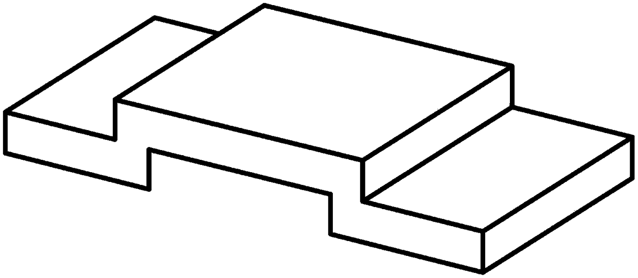
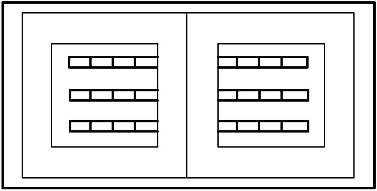
[0034] Figure 4 For wireless power transmission loose magnetic coupling transformer structure, including transmitting end metal plate 130, transmitting end insulating plate 140, transmitting end magnetic core 120, transmitting end coil 110, receiving end metal plate 230, receiving end coils 210 and 211, receiving end The magnetic core 220 and the insulating plate 240 at the receiving end. The transmitting and receiving device of the loose magnetic coupling transformer is formed by winding multiple litz wires in parallel, especially in this embodiment, the transmitting coil 110 is uniformly wound on the upper and lower surfaces of the insulating plate; the receiving coils 210 and 211 a...
Embodiment 2
[0043] Figure 7 For wireless power transmission loose magnetic coupling transformer structure, including transmitting end metal plate 130, transmitting end insulating plate 140, transmitting end magnetic core 120, transmitting end coils 110 and 111, receiving end metal plate 230, receiving end coil 210, receiving end The magnetic core 220 and the insulating plate 240 at the receiving end. The transmitting and receiving device of the loose magnetic coupling transformer is formed by winding multiple Litz wires in parallel. Especially in this embodiment, the receiving coil 210 is uniformly wound on the upper and lower surfaces of the insulating board, and the transmitting coils 110 and 111 are alternately wound on one side of the insulating board, and the arrangement of the coil positions should make the two coils Physical decoupling is achieved, that is, the mutual inductance between the two coils is approximately zero. In addition, the metal plate 130 at the transmitting end...
PUM
| Property | Measurement | Unit |
|---|---|---|
| thickness | aaaaa | aaaaa |
Abstract
Description
Claims
Application Information
 - R&D
- Intellectual Property
- Life Sciences
- Materials
- Tech Scout
- Unparalleled Data Quality
- Higher Quality Content
- 60% Fewer Hallucinations
Browse by: Latest US Patents, China's latest patents, Technical Efficacy Thesaurus, Application Domain, Technology Topic, Popular Technical Reports.
© 2025 PatSnap. All rights reserved.Legal|Privacy policy|Modern Slavery Act Transparency Statement|Sitemap|About US| Contact US: help@patsnap.com


