
Energy storage device and motor vehicle

A technology for accumulators and motor vehicles, which is applied in heat exchange equipment, lighting and heating equipment, power devices, etc., and can solve problems such as thermal contact being unevenly supplied to accumulator components

Inactive Publication Date: 2018-08-28
AUDI AG
View PDF13 Cites 3 Cited by
  • Summary
  • Abstract
  • Description
  • Claims
  • Application Information

AI Technical Summary

Problems solved by technology

[0007] The disadvantage of this cooling device is that good thermal contact between the accumulator elements to the cooling channels is not provided uniformly to all accumulator elements

Method used


Image

  • Energy storage device and motor vehicle
  • Energy storage device and motor vehicle
  • Energy storage device and motor vehicle

Examples


Embodiment Construction

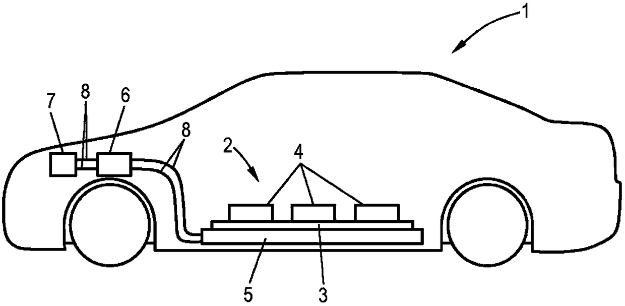
[0029] exist figure 1 The motor vehicle 1 shown in FIG. 1 has an energy storage device 2 which includes a plurality of energy storage elements 4 arranged on a radiator plate 3 . The accumulator device 2 is connected via a body part 5 to the cooling circuit of the motor vehicle 1 , the cooling circuit comprising a pump 6 , a heat exchanger 7 and coolant lines 8 . The coolant circulating in the cooling circuit is moved by means of the pump 6 so that the waste heat generated by the accumulator device 2 can be transferred via the heat exchanger 7 to the environment of the motor vehicle, which enables cooling of the accumulator device 2 .

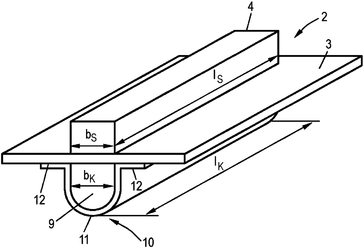
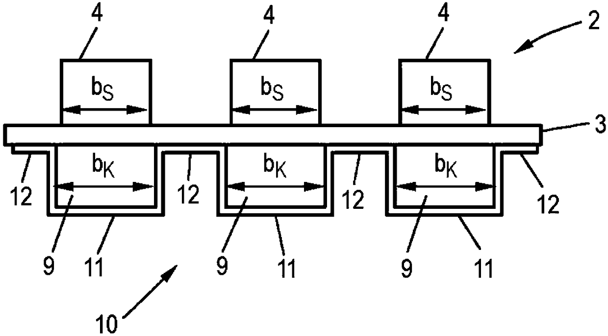
[0030] figure 2 shows a perspective view of an energy storage device 2 according to the invention, wherein an energy storage element 4 is arranged on one side of a cooling plate 3 , wherein on the side of the cooling plate 3 opposite to the energy storage element 4 The cooling channel 9 is formed by the channel member 10 fastened on the cool...


PUM


Abstract

The invention relates to an energy storage device, comprising at least one storage element with an associated cooling plate, with which the storage element is in thermal contact, as well as at least one channel component, which is fastened on the opposite-lying side of the cooling plate for the formation of at least one cooling channel through which a coolant can flow, wherein the cooling channelis at least as wide as and at least as long as the contact surface between the storage element and the cooling plate, wherein the cooling channel lies opposite the contact surface and covers it completely.

Description

technical field [0001] The invention relates to an energy storage device comprising at least one energy storage element with an associated cooling plate and at least one channel component with which the energy storage element is in thermal contact, the at least one channel component being fastened On opposite sides of the cooling plate for forming at least one cooling channel through which coolant can flow. Background technique [0002] Energy storage devices are used, for example, in motor vehicles with an electric drive, wherein the energy storage device serves to store the energy required for the electric drive. During operation, such an energy storage arrangement or the individual energy accumulators and electrically conductive components heat up considerably, so that the energy storage arrangement needs to be cooled. This cooling can be achieved, for example, by thermally connecting the energy storage device to a cooling system. [0003] Document DE 10 2012 209 306 A1...

Claims


Application Information

Patent Timeline
IPC IPC(8): H01M10/613H01M10/625H01M10/6554H01M10/6556H01M10/6567B60L50/64
CPCH01M10/613H01M10/625H01M10/6554H01M10/6556H01M10/6567H01M2220/20B60L50/64H01M50/249H01M10/66H01M10/6568B60K1/04B60K2001/005B60K2001/0438F28F3/12Y02E60/10
Inventor M·普法伊夫
Owner AUDI AG
Learn More