Cavity filter

A cavity filter and cavity technology, applied in the field of mobile communication, can solve the problems of large volume and weight

Active Publication Date: 2018-08-28
COMBA RF TECH GUANGZHOU LTD +1
View PDF5 Cites 1 Cited by
  • Summary
  • Abstract
  • Description
  • Claims
  • Application Information

AI Technical Summary

Problems solved by technology

[0004] Based on this, it is necessary to provide a more miniaturized and lighter cavity

Method used


Image

  • Cavity filter
  • Cavity filter
  • Cavity filter

Examples


Embodiment Construction

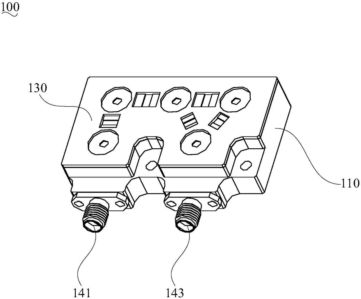
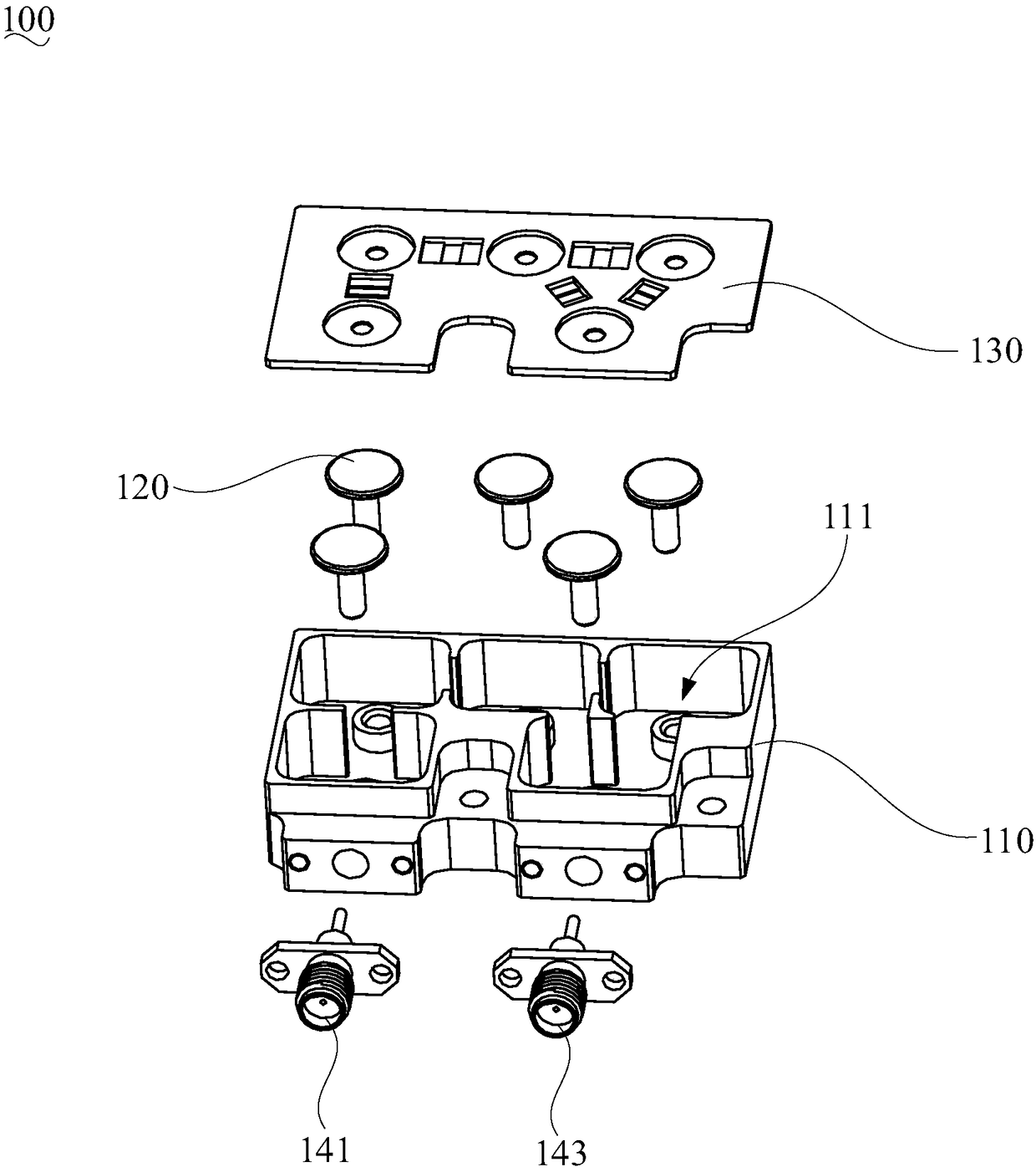
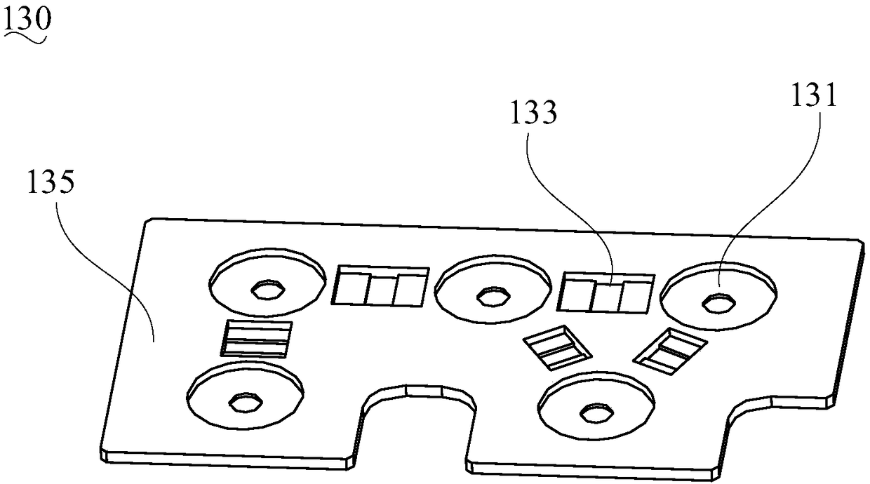
[0022] In order to facilitate the understanding of the present invention, the present invention will be described more fully below with reference to the relevant drawings. The drawings show preferred embodiments of the present invention. However, the present invention can be implemented in many different forms and is not limited to the embodiments described herein. On the contrary, the purpose of providing these embodiments is to make the understanding of the disclosure of the present invention more thorough and comprehensive.

[0023] It should be noted that when an element is referred to as being "fixed to" another element, it can be directly on the other element or a central element may also exist. When an element is considered to be "connected" to another element, it can be directly connected to the other element or an intermediate element may be present at the same time. The terms "vertical", "horizontal", "left", "right" and similar expressions used herein are for illustr...


PUM

PropertyMeasurementUnit
Thicknessaaaaaaaaaa
Apertureaaaaaaaaaa
Widthaaaaaaaaaa

Abstract

The present invention relates to a cavity filter. The cavity filter comprises a cavity internally provided with a plurality of resonant cavities, a cover plate capable of covering the cavity and a plurality of resonators respectively arranged in the resonant cavities and coupled to each other through preset coupling window. Frequency modulation areas are formed at positions of the cover plate corresponding to the resonators, coupling modulation areas are formed at positions of the cover plate corresponding to the coupling windows, and the frequency modulation areas and the coupling modulationareas can operably generate deformation. The frequency modulation areas and the coupling modulation areas respectively corresponding to the positions of the resonators and the coupling windows, capacitance and inductance parameters can be changed when the frequency modulation areas and the coupling modulation areas are convex upwards or concave downwards to achieve regulation of the frequency of the resonators and the coupling quantity between the resonators. Therefore, the cavity filter is provided with the frequency modulation areas and the coupling modulation areas on the cover plate to replace a traditional adjusting screw rod so as to effectively reduce the number of elements and simplify the structure, and the cavity filter is miniaturized and higher in light weight degree.

Description

Technical field [0001] The present invention relates to the technical field of mobile communication, in particular to a cavity filter. Background technique [0002] As a typical frequency selection device, the filter can effectively suppress useless signals, and play a role in signal selection, noise attenuation, and interference filtering. With the promotion of green energy and the growing demand for cost reduction, there is an increasing demand for low-cost filters. At the same time, with the rapid development of mobile communications, miniaturization and light weight have become the future development trend of microwave radio frequency devices. [0003] As a common filter, the cavity filter has the advantages of low cost and simple processing. However, in traditional cavity filters, metal tuning screws or coupling screws are often required to tune the frequency or coupling to compensate for errors caused by processing. However, the adjustment screw increases the volume and we...

Claims


Application Information

Patent Timeline
IPC IPC(8): H01P1/208
CPCH01P1/208
Inventor 张彪金志刚丁海
Owner COMBA RF TECH GUANGZHOU LTD
Why Eureka
Try Eureka