
Robot joint embedded electromagnetic braking harmonic speed reduction device and joint system

A technology of robot joints and electromagnetic braking, which is applied to the transmission device, transmission device parts, brake type, etc., can solve the problems of the robot's inability to work, affect the robot's effective load capacity, and troublesome robot operation and control, and achieve the moment of inertia Xiao Xiao, compact structure, and the effect of improving positioning accuracy and performance

Inactive Publication Date: 2022-04-22
成都瑞迪智驱科技股份有限公司
View PDF12 Cites 1 Cited by
  • Summary
  • Abstract
  • Description
  • Claims
  • Application Information

AI Technical Summary

Problems solved by technology

Because in high-acceleration or high-speed application scenarios, a large moment of inertia or greater inertia will be generated during the working process of the robot, resulting in abnormal situations such as inability to work or shortened service life of the robot.
The many parts of the robot joints lead to a complex structure, which makes the design and selection difficult, and the assembly process is cumbersome. At the same time, the matching effects of parts from different manufacturers are different, and it is difficult to find the best matching solution.
[0004] The pin-type brakes commonly used in robot joints are limited by the structure of the brake pawls. When braking, the input shaft cannot be braked quickly, and there is an excessive rotation, which causes the positioning accuracy of the robot to become worse and worse during operation.
At the same time, because its braking feature is a hard limit brake, this structure is more used in power-off protection and emergency braking conditions, and is not suitable for functional braking conditions. Not only does it vibrate greatly during braking, but also when it is released again There will also be a stuck situation when braking, which will cause great trouble to the operation and control of the robot
Limited by the size of the joints, the size of the electromagnetic brake coil and friction plate is small, resulting in insufficient braking torque, which affects the effective load capacity of the robot

Method used

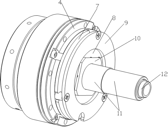
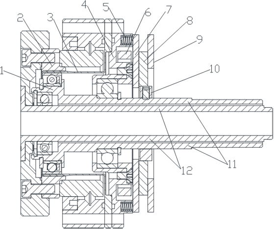
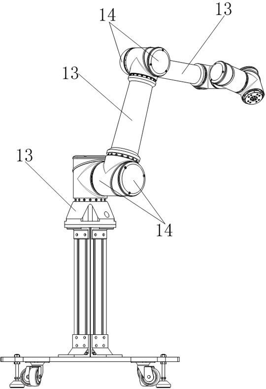

Image

  • Robot joint embedded electromagnetic braking harmonic speed reduction device and joint system
  • Robot joint embedded electromagnetic braking harmonic speed reduction device and joint system
  • Robot joint embedded electromagnetic braking harmonic speed reduction device and joint system

Examples


Embodiment

[0029] The electromagnetic braking harmonic deceleration device embedded in the robot joint and the joint system of the present invention mainly aim at the following technical shortcomings of the prior art: 1. Each component inside the robot joint is installed in the joint as an independent individual, and the degree of integration and light weight is low. The volume and mass are large, and the moment of inertia is large during high-speed operation, which affects the flexibility and working ability of the robot; 2. More parts lead to complex structures, resulting in difficulties in design and selection, cumbersome assembly processes, and the matching effect of parts from different manufacturers. 3. In order to achieve deceleration and drive in the traditional way, the two heat sources of the harmonic reducer and the driving motor are placed next to each other, and the high temperature condition affects the normal operation of the harmonic reducer, resulting in performance degrad...


PUM


Abstract

The robot joint embedded electromagnetic braking harmonic speed reducer comprises an input shaft and an output shaft rotationally installed in the middle of the input shaft, one side of the input shaft is a wave generating end, the other side of the input shaft is a braking end, and the wave generating end of the input shaft is provided with a wave generator; the brake end of the input shaft is provided with a rear end cover and a friction brake assembly, the rear end cover is provided with a coil groove and a spring installation groove, an electromagnetic coil is installed in the coil groove of the rear end cover in a matched mode, a spring is installed in the spring installation groove of the rear end cover, the spring is fixedly connected with a brake armature, and the friction brake assembly comprises a friction plate corresponding to the brake armature. The spring elastically drives the brake armature to cling to the friction plate for friction braking; a flexible gear is installed outside the wave generator in a matched mode, and a rigid gear is installed outside the flexible gear in a matched mode and connected with the output shaft. The optimal matching scheme of harmonic speed reduction and electromagnetic braking is provided, the integration degree and the lightweight degree are high, and the positioning precision and performance are improved.

Description

technical field [0001] The invention relates to the field of robot joint drive structures, in particular to a robot joint embedded electromagnetic brake harmonic deceleration device and a joint system. Background technique [0002] At present, the harmonic reducer, drive motor, brake and control board are arranged in sequence from front to back inside the common robot joints. These parts and components are usually purchased separately from various manufacturers and installed in the robot joint as a single individual. The structure needs to design the installation position and reserve clearance for each component in the robot joint shell, which leads to the design of the robot not only has a larger joint volume and weight; The inertia is also greater, and the performance of parts cannot be fully utilized, which affects the flexibility of the robot. The many parts of the robot joints lead to complex structures, making design selection difficult and the assembly process cumber...

Claims


Application Information

Patent Timeline
Patent Type & Authority Applications(China)
IPC IPC(8): F16H49/00F16H57/02F16H57/021F16D55/02F16D65/097F16D65/16B25J9/10B25J19/00F16D121/20
CPCF16H49/001F16H57/02F16H57/021F16D55/02F16D65/0975F16D65/16B25J9/1025B25J19/0004F16D2121/20F16H2057/02013F16H2057/02086
Inventor 杨军李星苏太郎肖平王荣春
Owner 成都瑞迪智驱科技股份有限公司
Learn More