Stator winding glue filling device and glue filling method thereof
A stator winding and glue filling technology, which is applied in the direction of electromechanical devices, electric components, and manufacturing motor generators, can solve the problems of uneven packaging structure of stator windings, inconvenient operation, and increased cleaning time, so as to save labor costs and materials Consumption, saving manpower and material resources, and reducing the effect of operating procedures
- Summary
- Abstract
- Description
- Claims
- Application Information
AI Technical Summary
Problems solved by technology
Method used
Image
Examples
Embodiment 1
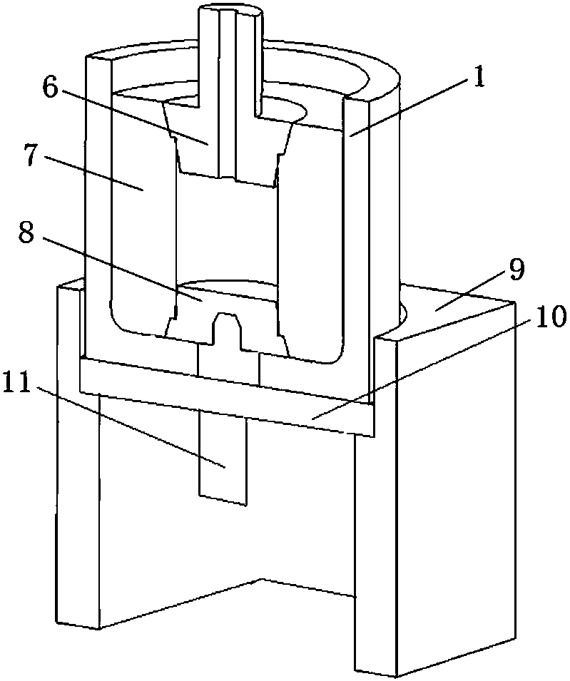
[0039] Such as figure 1 As mentioned above, a stator winding glue filling device includes an upper plug 6 and a lower plug 8 for respectively sealing the upper and lower ends of the axial cavity of the stator winding 7, and can allow the stator winding 7 to be inserted from the upper opening and the lower bottom plate is provided with a disassembly The sleeve 1 of the hole, and the bottom plug pad 10 that can be separately arranged at the disassembly hole and sealed, wherein, the upper plug 6 and the lower plug 8 are both frustum-shaped structures of silicone rubber materials, and the top of the upper plug 6 is set There is a cork handle, and there is an exhaust hole at the coaxial position of the upper plug 6 and the plug handle, which is used to discharge the air in the cavity when the upper plug 6 and the lower plug 8 seal the shaft cavity of the stator winding, so as to avoid the The air compression caused by the two plugs is not installed in place, and it can also be used...
Embodiment 2
[0044] Such as figure 2 As shown, the bottom blocking pad 10 is attached to the bottom surface of the lower bottom plate, that is, the bottom blocking pad 10 can make the bottom blocking pad 10 seal the disassembly hole and ensure that the bottom surface of the sleeve 1 is flat. 10 is removed from the bottom of the sleeve 1, and the bottom blocking pad 10 can adopt a cylindrical, conical or convex structure. Simultaneously, the lower surface of the bottom blocking pad 10 is fixedly provided with a detachable protruding handle 11, which is convenient for attaching the bottom blocking pad 10 to the bottom surface of the lower base plate, or conveniently moving the bottom blocking pad 10 out of the bottom surface of the lower base plate.
[0045] Further, the device also includes a support block 9 for supporting the block cavity structure of the sleeve 1 inserted into the stator winding 7, and is used for supporting the sleeve 1 when the stator winding is solidified.
[0046] A...
Embodiment 3
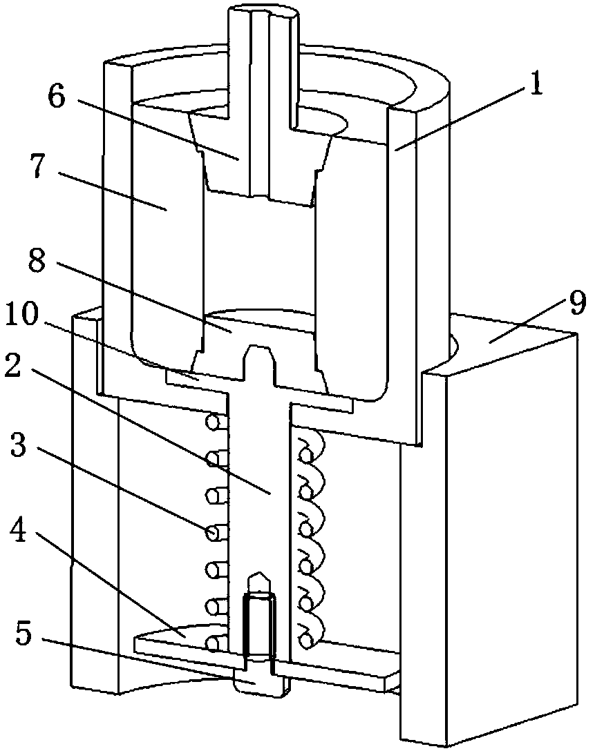
[0049] Such as figure 2 As shown, the bottom blocking pad 10 is attached to the lower bottom surface of the inner cavity of the sleeve 1, that is, the bottom blocking pad 10 can make The bottom blocking gasket 10 is removed from the bottom of the sleeve, and the bottom blocking gasket 10 can adopt a cylindrical, conical or convex structure. The lower surface of the bottom blocking pad 10 is fixedly provided with an ejector rod 2 passing through the disassembly hole, so that the stator winding 7 can be moved out of the sleeve 1 along the inner wall of the sleeve 1 by pushing the bottom blocking pad 10 upward.
[0050] The bottom plug-out pad is pulled out upwards, and the plug-out and ejection can be completed in one step, and the bottom plug pad with a larger cross-section ensures uniform ejection force and reduces damage to the plug-out. With cooperation, the disassembly of the lower blockage can also be directly realized, which is simple, controllable and convenient, and imp...
PUM
 Abstract
Description
Claims
Application Information
 - R&D
- Intellectual Property
- Life Sciences
- Materials
- Tech Scout
- Unparalleled Data Quality
- Higher Quality Content
- 60% Fewer Hallucinations
Browse by: Latest US Patents, China's latest patents, Technical Efficacy Thesaurus, Application Domain, Technology Topic, Popular Technical Reports.
© 2025 PatSnap. All rights reserved.Legal|Privacy policy|Modern Slavery Act Transparency Statement|Sitemap|About US| Contact US: help@patsnap.com


