Hot metal ladle

A technology of ladle and cover, which is applied to casting melt containers, metal processing equipment, casting equipment, etc., can solve the problems of flue gas overflow, poor insulation effect of ladle during casting, and solidification of molten iron in the ladle.

Inactive Publication Date: 2018-08-31
苏州勤美达精密机械有限公司
View PDF8 Cites 4 Cited by
  • Summary
  • Abstract
  • Description
  • Claims
  • Application Information

AI Technical Summary

Problems solved by technology

Due to the viscous characteristics of the molten iron, the slag is not easy to float to the surface of the molten iron in a short time, and part of it is suspended in the middle of the molten iron. After the molten iron is smelted, the slag collector can only remove most of the floating on the surface of the molten iron. slag, so that when pouring, the slag suspended in the molten iron will enter the mold with the molten iron, which will eventually lead to slag inclusion defects in the casting, and sometimes the molten iron ladle will be damaged due to the small size of the casting to be cast and the long casting time. Poor thermal insulation effect will cause the molten iron in the ladle to solidify, affecting casting
[0004] At present, the ladles used in large, medium and small iron factories in my country are only filled with refractory bricks in the ladle, and a layer of coating made of refractory cement and castable is applied to the refractory bricks, and then sprayed on the coating. layer of paint, after a period of use, the paint in the iron ladle will be covered with molten iron slag, and the slag will be removed, resulting in an increase in production costs
At the same time, due to the unreasonable design, the distance between the column of the molten iron ladle and the ladle cover is too small, resulting in the short distance between the furnace nozzle and the molten iron ladle when the molten iron is tapped, and the phenomenon of flue gas overflow and nodulizer splashing is serious; the gap between the ladle mouth and the beam If the spacing is too small, if the operation is not careful when tapping the molten iron, the cover is easy to be pressed against the beam, causing an accident

Method used


Image

  • Hot metal ladle
  • Hot metal ladle
  • Hot metal ladle

Examples


Embodiment Construction

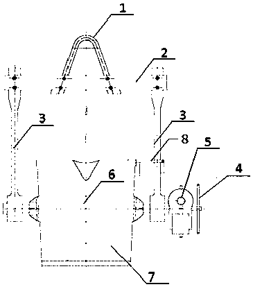
[0020] The present invention will be specifically introduced below in conjunction with the accompanying drawings and specific embodiments.

[0021] In describing the present invention, it should be understood that the terms "center", "longitudinal", "transverse", "upper", "lower", "front", "rear", "left", "right", " The orientations or positional relationships indicated by "vertical", "horizontal", "top", "bottom", "inner" and "outer" are based on the orientations or positional relationships shown in the drawings, and are only for the convenience of describing the present invention and Simplified descriptions, rather than indicating or implying that the device or element referred to must have a particular orientation, be constructed and operate in a particular orientation, and thus should not be construed as limiting the invention. In addition, the terms "first" and "second" are used for descriptive purposes only, and should not be understood as indicating or implying relative...


PUM


Abstract

The invention discloses a hot metal ladle comprising a hot metal ladle body, a ladle shaft assembly, a supporting assembly and a ladle cover assembly. The ladle shaft assembly comprises a handle, a turbine reducer and a ladle shaft which are all connected in sequence, the ladle shaft penetrates through the hot metal ladle body, and the angle of the hot metal ladle body is adjusted through the handle. The supporting assembly comprises a liftinghook, a cross beam and two vertical columns, the liftinghook is mounted on the cross beam, and the two vertical columns are located on the two sides of the hot metal ladle body correspondingly and vertically connected with the two ends of the ladle shaft. The cross beam is vertically connected between the vertical columns, the ladle cover assembly comprises a ladle cover, a bent beam, a connecting shaft and a supporting rod which are connected in sequence, and a spring is connected between the bent beam and the hot metal ladle body. According to the hot metal ladle, the supporting rod of the ladle cover assembly is used for supporting the ladle cover, the buffering effect of the spring can effectively reduce impact to the ladle body when the ladle cover is closed, and thus hot metal is prevented from being spilled.

Description

technical field [0001] The invention relates to the field of iron and steel smelting, in particular to a ladle for casting. Background technique [0002] Casting refers to the method of casting liquid metal into a casting cavity that is suitable for the shape of the part, and after it is cooled and solidified, the part or blank is obtained. Ladles are widely used in foundries, etc., to receive molten iron in front of open hearth furnaces, electric furnaces or converters, and perform pouring operations. When pouring molten iron, the molten iron at the tap nozzle will easily flow to the ladle along the wall, causing deformation of the ladle. And because the molten iron temperature is high, it is easy to cause the tape to crack. [0003] In the casting process, the main operation of the smelting process is to add scrap steel and returned materials to the intermediate frequency induction furnace for melting. Since the metallurgical raw materials contain a large amount of refrac...

Claims


Application Information

Patent Timeline
Patent Type & Authority Applications(China)
IPC IPC(8): B22D41/06B22D41/04
CPCB22D41/06B22D41/04
Inventor 杨林山
Owner 苏州勤美达精密机械有限公司
Why Eureka
Try Eureka