
Filter element having two filter media

A technology of filter media and filter elements, which can be used in filter circuits, filter separation, cartridge filters, etc., and can solve problems such as loosening and damage.

Active Publication Date: 2018-08-31
ROBERT BOSCH GMBH
View PDF8 Cites 2 Cited by
  • Summary
  • Abstract
  • Description
  • Claims
  • Application Information

AI Technical Summary

Problems solved by technology

However, this can lead to the situation that the working fluid flows through the filter element in the return flow and the filtered particles are thus loosened from the filter element.
Loose particles can then reach the pump and damage it

Method used


Image

  • Filter element having two filter media
  • Filter element having two filter media
  • Filter element having two filter media

Examples


Embodiment Construction

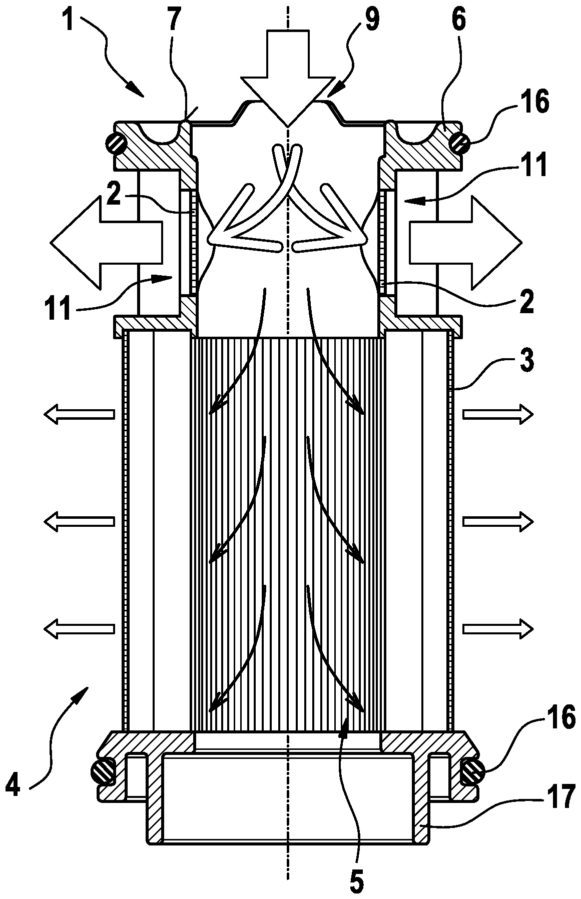
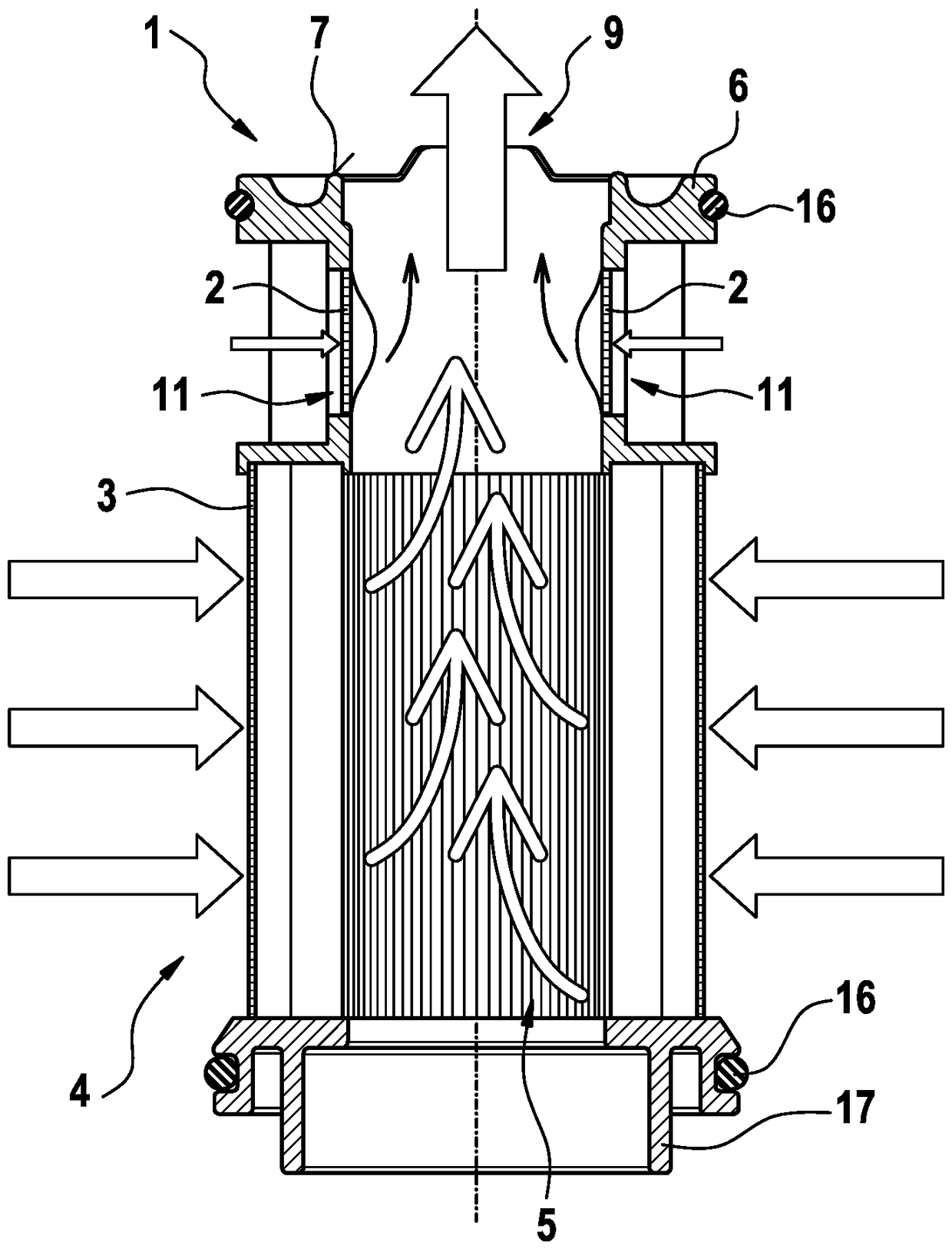
[0042] figure 1 A filter element 1 according to an exemplary embodiment of the invention is shown schematically in an exploded view. figure 2 yes figure 1 A cross-sectional view along the section line A-A.

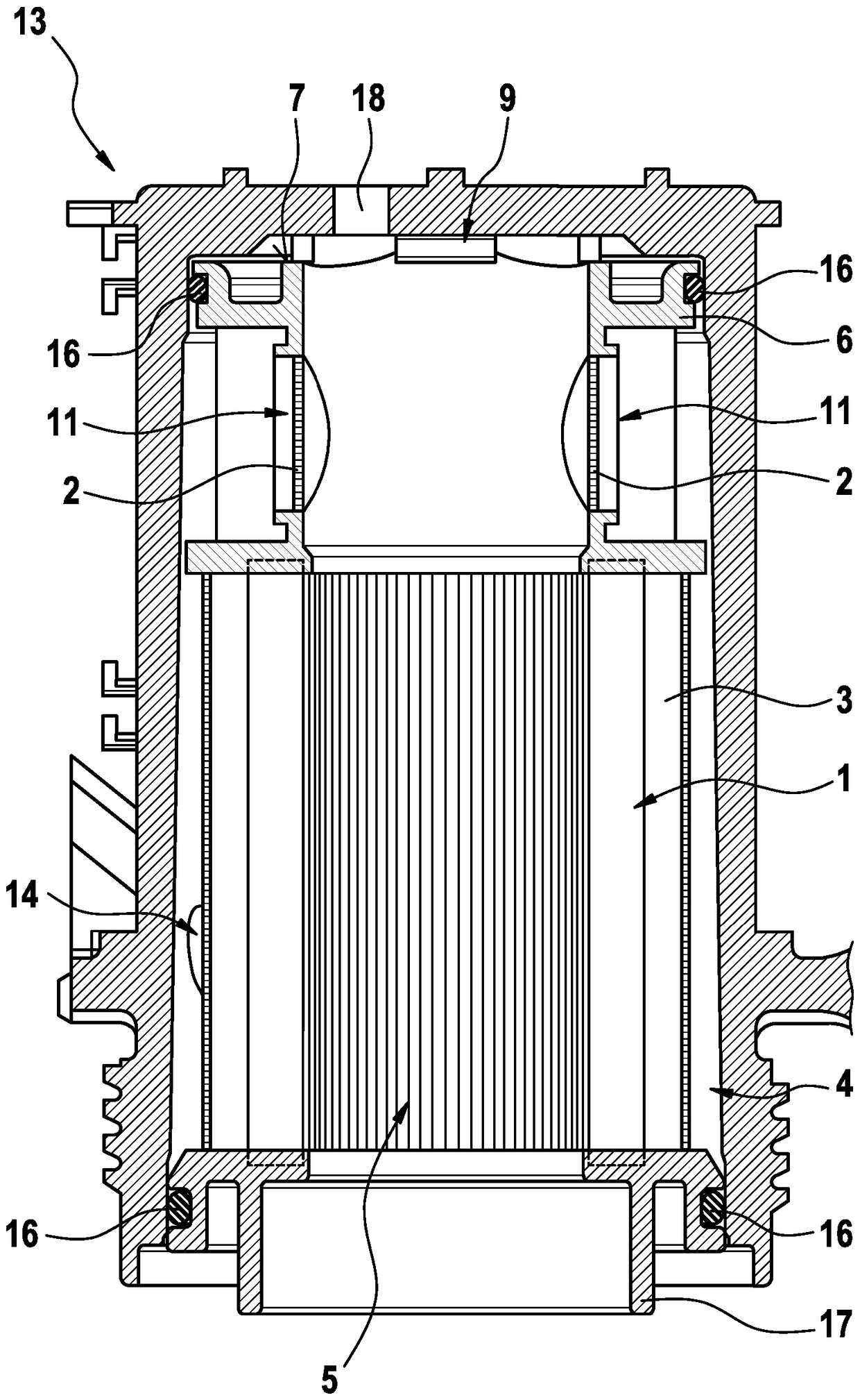
[0043] The filter element 1 comprises a first filter medium 2 and a second filter medium 3 . The first filter medium 2 can be differentiated from the second filter medium 3 , in particular the first filter medium 2 and the second filter medium 3 have different filter characteristics. In particular, the first filter medium 2 is a surface filter and the second filter medium 3 is a depth filter. Furthermore, the filter element 1 has a cover element 6 . The cover element 6 is arranged on the second filter medium 3 and serves to receive the first filter medium 2 . The cover element 6 and the second filter medium 3 are connected to one another in a fluid-tight manner here.

[0044] The second filter medium 3 is configured as a hollow cylinder. It is provided here that th...


PUM


Abstract

The invention relates to a filter element (1), comprising a first filter medium (2) and a second filter medium (3), wherein the filter element (1) has an non-filtering side (4), via which a fluid canbe input, and a filtering side (5), via which the fluid can be output, wherein the first filter medium (2) and the second filter medium (3) are arranged between the non-filtering side (4) and the filtering side (5), and wherein the first filter medium (2) has a lower relative pressure drop than the second filter medium (3) in a fluid flow direction from the filtering side (5) to the non-filteringside (4).

Description

technical field [0001] The invention relates to a filter element. Furthermore, the invention relates to a filter module comprising such a filter element. It is provided here that fluid can be filtered by the filter element. Background technique [0002] Filter elements are known from the prior art. The filter element is used if the system to be supplied with the working fluid reacts sensitively to contamination of the working fluid. With the filter module, such contamination can be avoided. In particular, such filter elements are used in motor vehicles for filtering urea or fuels such as diesel or petrol, which are respectively used as the operating medium of the vehicle. [0003] Depending on the freezing point of the fluid to be filtered, it can happen that the fluid (eg urea solution) freezes or coagulates (eg diesel) at low outside temperatures. In order to prevent this, the filter module and / or the filter element can be designed as a heatable structure, which incre...

Claims


Application Information

Patent Timeline
Patent Type & Authority Applications(China)
IPC IPC(8): B01D36/00B01D27/14B01D29/15B01D29/21B01D29/54B01D29/66
CPCB01D36/003B01D27/144B01D29/15B01D29/21B01D29/54B01D29/66Y02T10/12Y02A50/20B01D46/10B01D2321/2083
Inventor M.马蒂内斯戈梅斯M.卡斯特容洛佩斯R.塔费尔J.L.阿里亚斯阿里亚斯J.奥塔哈尔S.迪亚斯曼萨内罗D.艾萨帕拉
Owner ROBERT BOSCH GMBH
Learn More