Fixed-length cutting device for tubular part

A cutting device and part technology, applied in the field of fixed-length cutting devices for tubular parts, can solve the problems affecting the processing of tubular parts, errors, and inability to guarantee the same length of tubular parts, and achieve the effect of improving work efficiency and continuous cutting

Active Publication Date: 2018-09-04
宁波鑫神泽汽车零部件有限公司
View PDF4 Cites 16 Cited by
  • Summary
  • Abstract
  • Description
  • Claims
  • Application Information

AI Technical Summary

Problems solved by technology

The problem with this cutting method is that when the cutter moves to the long tube for cutting, the long tube is moving, which leads to errors due to the movement of the cutter every time cutting, and if the moving speed of the cutter changes , it cannot guarantee that each tubular part is the same length, and the cutter moves horizontally, but the cutter generally cuts downwards, which causes the end of the long tube to be inclined when the cutter cuts the long tube , instead of a plane perpendicular to the axial direction of the long tube, which affects the processing of subsequent tubular parts

Method used


Image

  • Fixed-length cutting device for tubular part
  • Fixed-length cutting device for tubular part
  • Fixed-length cutting device for tubular part

Examples


Embodiment 1

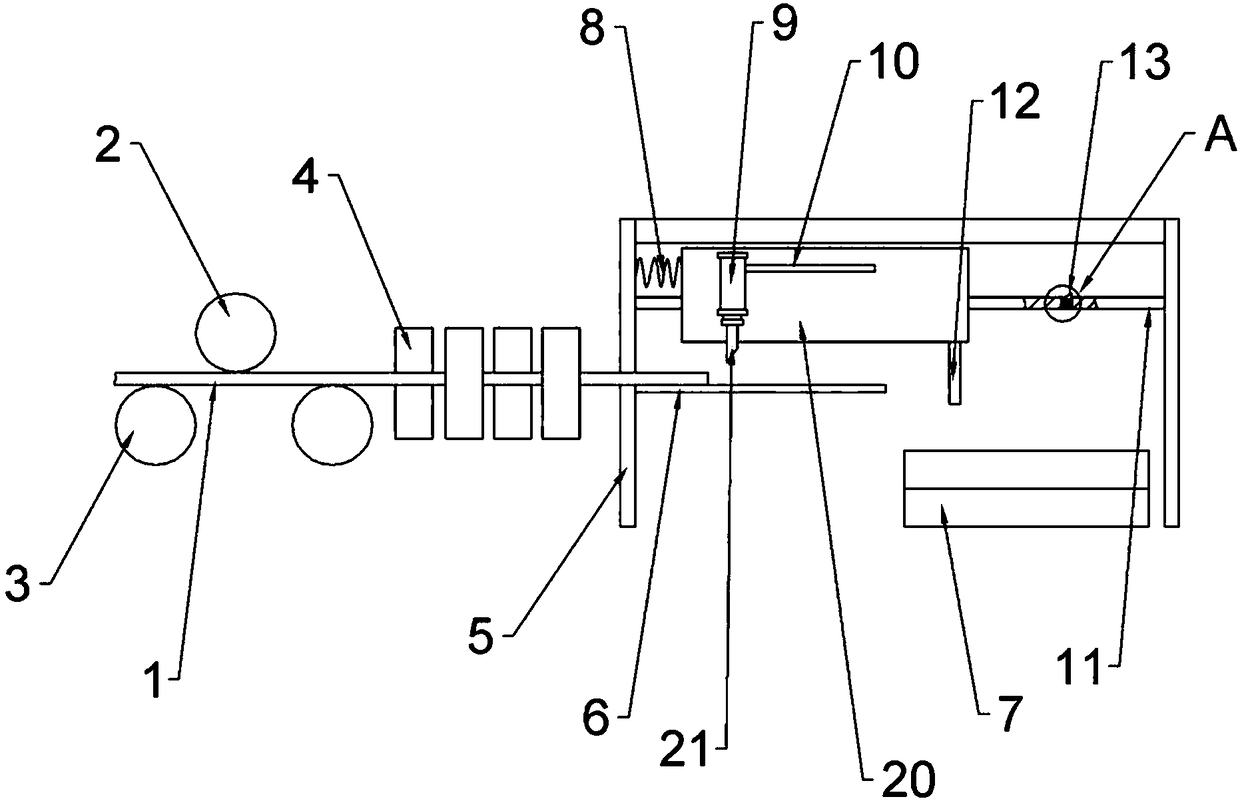
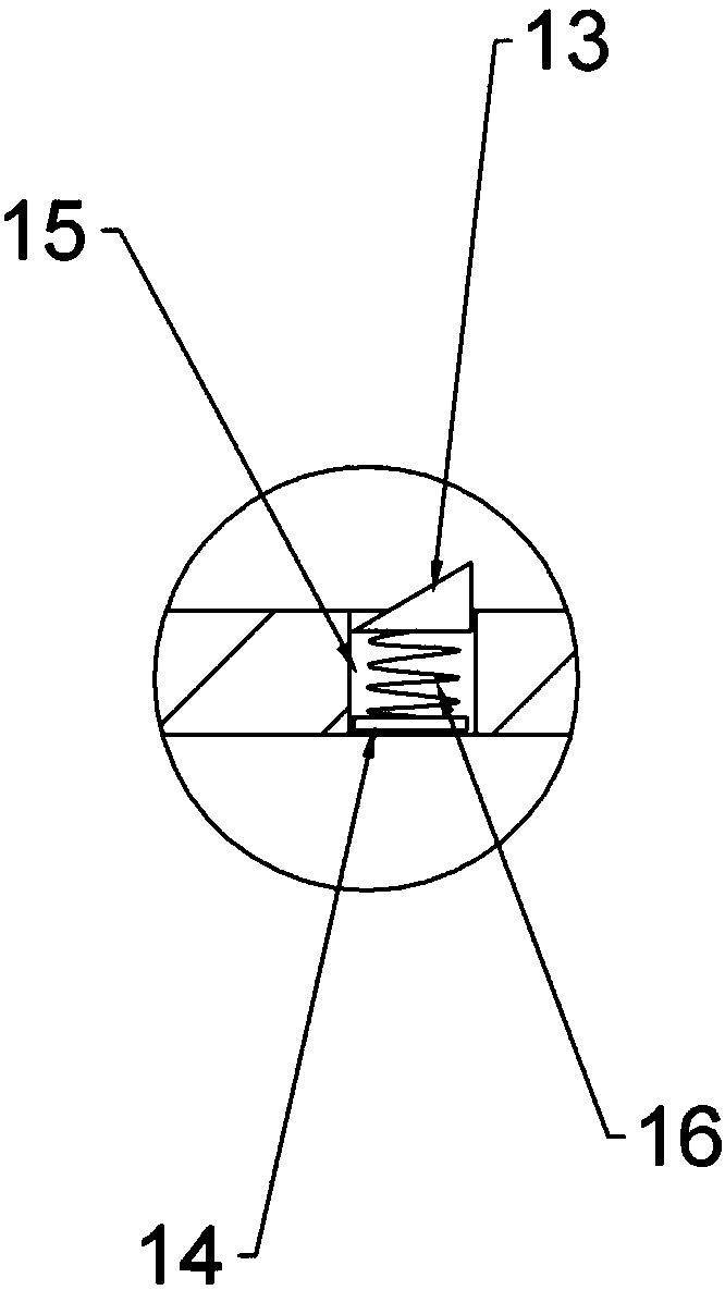
[0021] This embodiment is basically as attached figure 1 and figure 2 Shown: a fixed-length cutting device for tubular parts, including a frame 5, a cutter 21 and a long tube delivery mechanism for delivering the long tube 1, and the long tube delivery mechanism is on one side of the frame 5. The long pipe conveying mechanism includes a plurality of conveying rollers 3 , on which the long pipe 1 is placed to realize transmission, and above the conveying rollers 3 there is also a pressure roller 2 for pressing the long pipe 1 . Cutter 21 is located on frame 5 . A squeeze roller 4 is also arranged between the frame 5 and the long pipe conveying mechanism, and the squeeze roller 4 is used to straighten the long pipe 1 to avoid bending of the long pipe 1 . An elastic member and a slide rail 11 are also provided on the frame 5 , and the elastic member is a spring 8 in this embodiment. The slide rail 11 is slidably connected with a slide seat 20, the slide seat 20 is provided wi...

Embodiment 2

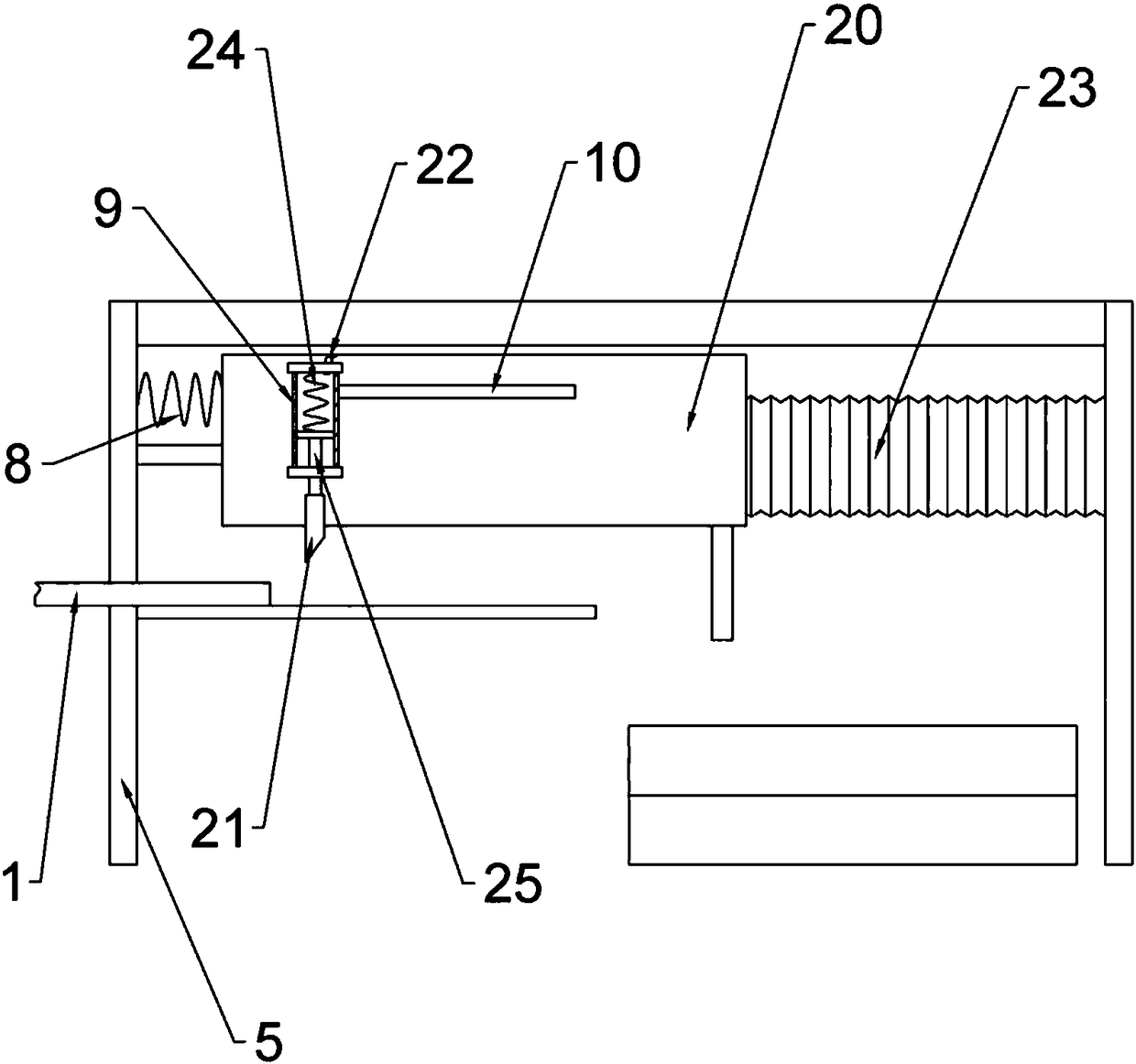
[0025] Such as image 3 and Figure 4As shown, the difference between this embodiment and Embodiment 1 is that it further includes an elastic bellows 23 , one end of the elastic bellows 23 is sealed and fixedly connected with the sliding seat 20 , and the other end is sealed and fixedly connected with the frame 5 . Cylinder 9 comprises cylinder body, and sealing slide is connected with piston in the cylinder body, and piston is provided with piston rod 25, is provided with extension spring 24 on piston and cylinder 9 top walls, and piston rod 25 lower ends are connected with cutter 21. The cylinder body communicates with the elastic bellows 23 through a communication pipe 22 . Because the two ends of the elastic bellows 23 are respectively sealed and fixed to the sliding seat 20 and the frame 5, when the sliding seat 20 slides to the right under the drive of the long tube 1 and the baffle 12, the elastic bellows 23 will be squeezed, The air pressure in the elastic bellows 23...


PUM


Abstract

The invention belongs to the field of machining devices of automobile parts and particularly discloses a fixed-length cutting device for a tubular part. The fixed-length cutting device for the tubularpart comprises a rack, a cutter and a long pipe conveying mechanism for conveying a long pipe. The long pipe conveying mechanism is located on one side of the rack, the cutter is arranged on the rack, and the fixed-length cutting device for the tubular part further comprises an elastic part. The rack is provided with a sliding rail, the sliding rail is in sliding connection with a sliding seat, abaffle capable of abutting against the long pipe is arranged on the sliding seat, the baffle is perpendicular to the sliding rail, an air cylinder is arranged on the sliding seat and connected with apiston rod, and the piston rod is fixedly connected with the cutter which is parallel to the baffle. One end of the elastic part is connected with the sliding seat, and the other end of the elastic part is fixedly connected with the rack. The rack is provided with a control part capable of controlling the piston rod of the air cylinder to stretch out, and the sliding seat can trigger the controlpart. The device can achieve fixed-length cutting of the tubular part and ensures that all parts have the same length.

Description

technical field [0001] The invention relates to the field of processing devices for automobile parts, in particular to a fixed-length cutting device for tubular parts. Background technique [0002] Along with the advancement of science and technology and the development of economy, the use of automobiles, especially cars, is becoming more and more common, and people's dependence on automobiles is also increasing when traveling. Therefore, the current automobile industry is developing rapidly, and it has driven the development of related industries, such as the auto parts industry. Auto parts can be divided into engine parts, transmission parts, brake parts, steering parts, walking parts, etc. according to their performance, and can be divided into plate parts, tubular parts, etc. according to their shape. [0003] The material of tubular parts is mostly iron. For tubular parts, there are certain requirements for the length during use, that is, the length of the tubular par...

Claims


Application Information

Patent Timeline
Patent Type & Authority Applications(China)
IPC IPC(8): B23D21/00B23D36/00B23Q7/00
Inventor 王健
Owner 宁波鑫神泽汽车零部件有限公司
Why Eureka
Try Eureka