
Automatic welding equipment capable of improving welding precision

A technology of automatic welding and welding accuracy, which is applied in the direction of welding equipment, welding equipment, auxiliary welding equipment, etc., can solve the problems that affect the processing quality of precision devices, cannot guarantee the welding accuracy requirements of precision devices, and cannot guarantee the welding accuracy, so as to achieve flexibility high effect

Inactive Publication Date: 2018-09-04
CHENGDU RONGCHUANG ZHIGU SCI & TECH
View PDF1 Cites 2 Cited by
  • Summary
  • Abstract
  • Description
  • Claims
  • Application Information

AI Technical Summary

Problems solved by technology

While satisfying the welding and cutting operation functions of traditional robots, this technical solution can solve the continuous cutting of complex closed surfaces and the continuous and repeated welding of complex closed curves. However, this technical solution still has the following shortcomings: the welding accuracy cannot be guaranteed, so it cannot The welding accuracy requirements for some precision devices, especially for the welding of thin metal sheets in the processing and production of some precision devices, directly affect the processing quality of precision devices

Method used


Image

  • Automatic welding equipment capable of improving welding precision
  • Automatic welding equipment capable of improving welding precision
  • Automatic welding equipment capable of improving welding precision

Examples


Embodiment Construction

[0029] In order for those skilled in the art to better understand the present invention, the present invention will be further described in detail below in conjunction with the accompanying drawings and the following embodiments.

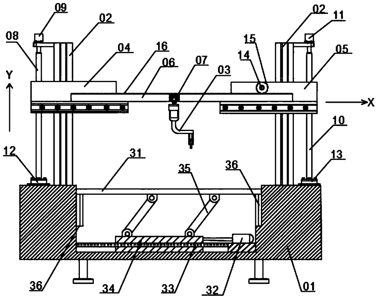
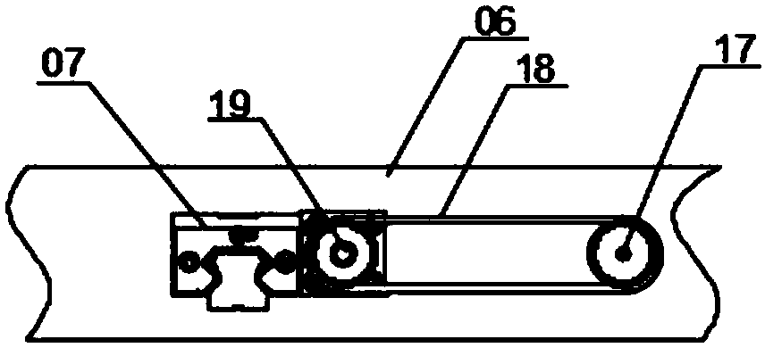
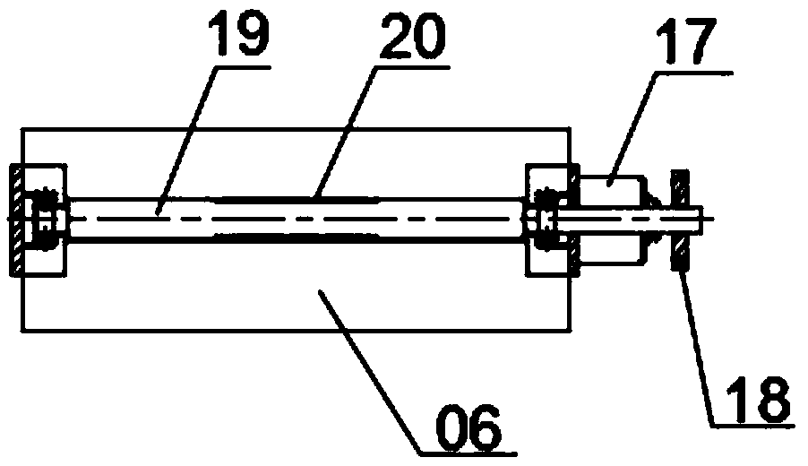
[0030] Please refer to figure 1 As shown, this embodiment provides an automatic welding device that can improve welding accuracy, including a base 01 and a gantry mechanism arranged on the base 01 and a welding mechanism 03 cooperating with the gantry mechanism. The gantry mechanism includes a gantry frame and Drive the welding mechanism 03 to move the X-axis travel assembly, the Y-axis travel assembly and the Z-axis travel assembly along the X-axis direction, the Y-axis direction and the Z-axis direction respectively. Specifically, the gantry includes two vertical columns 02, two vertical The upright columns 02 are arranged at the left and right ends of the base 01, and the upper ends of the two upright columns 02 are respectively sleeved with a le...


PUM


Abstract

The invention discloses automatic welding equipment capable of improving welding precision, and relates to the field of welding automation. The automatic welding equipment capable of improving the welding precision solves the defects that in the prior art, the welding precision requirements of sheet metal in precision devices cannot be ensured. The automatic welding equipment comprises a base, a gantry mechanism disposed on the base and a welding mechanism disposed on the gantry mechanism. The welding mechanism is separately driven by an X-axis traveling assembly, a Y-axis traveling assembly and a Z-axis traveling assembly which move in the X-axis direction, the Y-axis direction, and the Z-axis direction. The welding mechanism comprises a welding gun, an X-axis rotating assembly for driving the welding gun to rotate along the X-axis and a Y-axis rotating assembly for driving the welding gun to rotate along the Y-axis separately. The welding gun is provided with a laser tracking systemand a spectral confocal sensor, and the laser tracking system comprises a laser device and a monitoring lens. By implementing the technical scheme, different sheet metal can be flexibly welded, and the sheet metal in the precision device processing and production process can be accurately welded to ensure the welding precision requirements of the sheet metal in the precision devices.

Description

technical field [0001] The invention relates to the field of welding automation, and more specifically relates to an automatic welding device capable of improving welding precision. Background technique [0002] Straight sealing and circular seams are the most common welding seams in tailor welding of steel plates, which put forward higher requirements not only in terms of welding strength, precision, efficiency, appearance, etc. for sheet metal welding in the process of precision device processing and production. As an important fine processing method, laser welding has the advantages of narrow weld seam, small heat-affected zone, high welding precision, and smooth weld seam. It has been widely used in the welding of various metal sheets, such as welding of minimally invasive medical device components, Welding packaging of small sensor parts, fuel cell metal diaphragm welding packaging, precision welding packaging of special sensor components, and welding packaging of FBG f...

Claims


Application Information

Patent Timeline
IPC IPC(8): B23K31/02B23K37/00
CPCB23K31/02B23K37/00
Inventor 章显红
Owner CHENGDU RONGCHUANG ZHIGU SCI & TECH
Learn More