Automatic press-in machine for gear and drive pin

A gear-driven, press-in machine technology, used in metal processing, metal processing equipment, manufacturing tools, etc., can solve the problems of low work efficiency, difficulty in ensuring production quality, and high labor intensity, so as to ensure production quality and improve work. Efficiency and degree of automated production, the effect of reducing labor intensity and labor costs

Pending Publication Date: 2018-09-04
珠海大利刀具有限公司
View PDF0 Cites 5 Cited by
  • Summary
  • Abstract
  • Description
  • Claims
  • Application Information

AI Technical Summary

Problems solved by technology

[0002] The gear pin shaft assembly method currently on the market is usually to fix the gear on a plane, and the plane is provided with a groove matching the shaft center hole of the gear, and the pin shaft is pressed into the gear by manual knocking or operating a press In the size of the hole, this method is inefficient, labor-intensive, and, due to the uncertainty of the personnel, it is difficult to guarantee the production quality

Method used


Image

  • Automatic press-in machine for gear and drive pin
  • Automatic press-in machine for gear and drive pin
  • Automatic press-in machine for gear and drive pin

Examples


Embodiment Construction

[0022] The present invention will now be described in further detail with reference to the accompanying drawings and preferred embodiments.

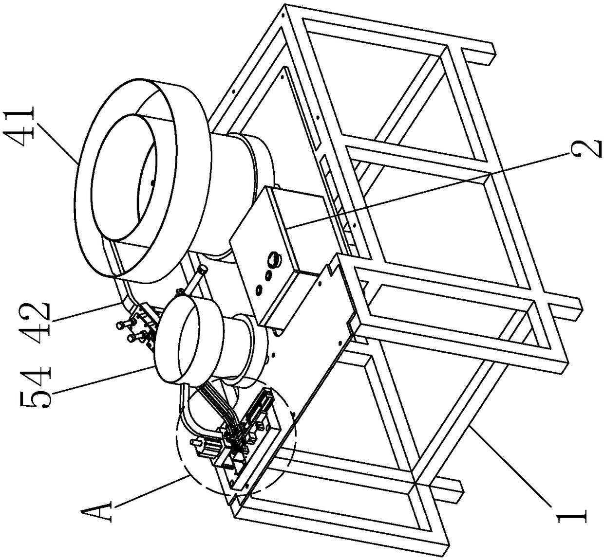
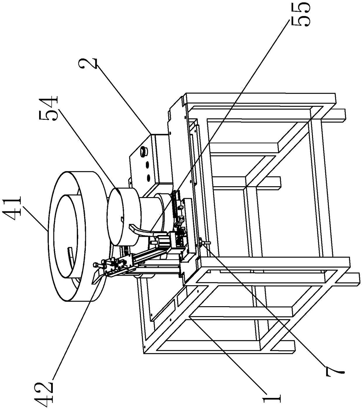
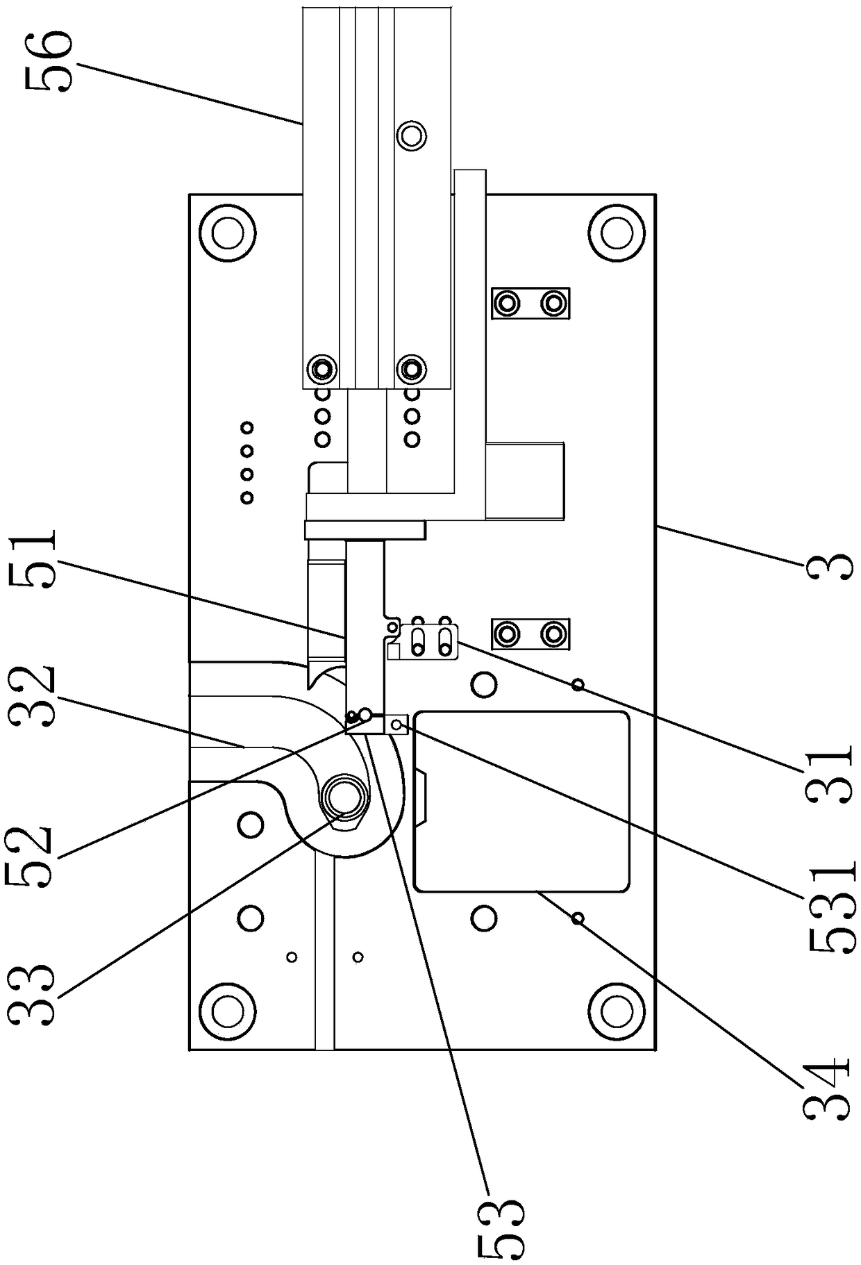
[0023] A gear-driven pin automatic press-in machine, such as figure 1 , figure 2 and Figure 5 As shown, it includes a base 1 and an electric control box 2, and the base 1 is provided with a fixed plate 3 and a first feeding mechanism, a second feeding mechanism, a press-fitting mechanism 6 and The ejector mechanism 7, the electric control box 2 may include a programmable controller or a PLC controller or a single-chip microcomputer, the fixing plate 3 is horizontally fixed on the base 1 through a screw connection, and the fixing plate 3 is provided with a machining groove 32. The output ends of the first feeding mechanism and the second feeding mechanism are respectively connected to the processing groove 32. The processing groove 32 is provided with an ejection hole 33, and the pressing mechanism 6 is vertically arranged above the p...


PUM


Abstract

The invention relates to the technical field of gear pin shaft press fitting, in particular to an automatic press-in machine for a gear and a drive pin. The automatic press-in machine comprises a base, an electric control box, a machining groove formed in the base, a first feed mechanism, a second feed mechanism, a press fitting mechanism and an ejection mechanism, wherein the first feed mechanism, the second feed mechanism, the press fitting mechanism and the ejection mechanism are electrically connected with the electric control box; the first feed mechanism comprises a steering assembly andis connected with the machining groove; and the second feed mechanism comprises a sliding block capable of moving in the horizontal direction, and the sliding block is provided with a feed through hole accommodating the drive pin moving in the vertical direction. The first feed mechanism and the second feed mechanism are adopted to convey the gear and the drive pin to a fixed plate, the drive pinis pressed into a size hole corresponding to the gear through the press fitting mechanism to realize automatic press-in, the work efficiency and the automated production degree are promoted, the production quality is guaranteed, and the manual labor intensity and the labor cost are reduced.

Description

technical field [0001] The invention relates to the technical field of gear pin shaft pressing, in particular to an automatic pressing machine for gear driving pins. Background technique [0002] At present, the gear pin assembly method on the market is usually to fix the gear on a plane, and the plane is provided with a groove that matches the shaft hole of the gear. Manually knock the pin or operate the press to press the pin into the gear. In this way, the work efficiency is low, the manual labor intensity is high, and due to the uncertainty of personnel, it is difficult to ensure the production quality. SUMMARY OF THE INVENTION [0003] The technical solution adopted by the present invention to solve the above problems is to provide an automatic press-in machine for gear drive pins, which includes a base and an electric control box, and is characterized in that it also includes a machining groove arranged on the base and The first feeding mechanism, the second feeding...

Claims


Application Information

Patent Timeline
Patent Type & Authority Applications(China)
IPC IPC(8): B23P19/02B23P19/00
CPCB23P19/02B23P19/001B23P19/002
Inventor 谢松
Owner 珠海大利刀具有限公司
Why Eureka
Try Eureka