
Special clamp for drilling mechanism

A technology of drilling mechanism and special fixture, which is applied in the direction of boring/drilling, drilling/drilling equipment, clamping, etc., which can solve the problems of long manufacturing cycle, affecting work efficiency, and difficulty in ensuring accuracy, so as to reduce operation cost, improve construction efficiency, and increase benefits

Active Publication Date: 2018-09-04
NINGBO C S I POWER CO LTD
View PDF6 Cites 1 Cited by
  • Summary
  • Abstract
  • Description
  • Claims
  • Application Information

AI Technical Summary

Problems solved by technology

Not only is the manufacturing cycle long, the accuracy is difficult to guarantee, and the technical requirements for installation and adjustment are high, but also the fixture using the V-shaped block as the positioning element is difficult to be compact in structure, and it is impossible to accurately complete the positioning operation, which seriously affects the work efficiency.

Method used


Image

  • Special clamp for drilling mechanism
  • Special clamp for drilling mechanism
  • Special clamp for drilling mechanism

Examples


Embodiment 1

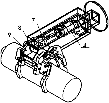
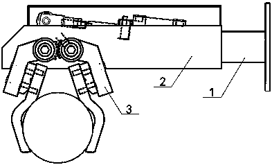
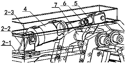
[0021] Embodiment 1: This embodiment discloses a special fixture for a drilling mechanism. The special fixture for the drilling mechanism includes a connecting body 1, which is fixedly connected to the drilling mechanism. The front end of the connecting body 1 is provided with a drive carrying box 2. The driving body 2 is provided with a driving body, which is connected to the clamping body 3. The driving body includes a hydraulic drive assembly 4, a drive link 5 connected to the hydraulic drive assembly 4, and a drive pendulum connected to the drive link 5. Rod 6, the first rotating rod 7 that links to each other with driving fork 6, the second rotating rod 8 that cooperates with the first rotating rod 7, clamping body 3 comprises driving folded rod 3-1, and drive folded rod 3-1 phase The connected transition connecting plate 3-2, the clamping claw 3-3 connected with the transition connecting plate 3-2, the connecting body 1 includes the connecting plate 1-1 and the connecting...

Embodiment 2

[0031] Embodiment 2: This embodiment discloses a drilling mechanism, which includes the special clamp disclosed in Embodiment 1. Specifically, the steps for using the drilling mechanism are as follows:

[0032] A. According to the size of the cylindrical workpiece to be clamped, the displacement of the liquid displacement device is changed to control the expansion and contraction of the piston rod of the hydraulic cylinder.

[0033] B. The reciprocating motion of the piston rod of the hydraulic cylinder drives the coordinated movement of the driving connecting rod, the movement of the driving connecting rod drives the swing of the driving swing rod, and the swing of the driving swing rod prompts the rotation of the first rotating rod, and the first ratchet of the first rotating rod and The second ratchet is engaged with the transmission, thereby driving the rotation of the second rotating rod,

[0034] C. The movement of the first rotating rod and the second rotating rod driv...


PUM


Abstract

The invention discloses a special clamp for a drilling mechanism. According to the special clamp, the problem of clamping a cylindrical workpiece is solved, through the cooperative operation between ahydraulic driving assembly and a connecting rod assembly, the limitation that when a current drilling machine clamps the cylindrical workpiece, the clamping capacity is poor, the efficiency is low and the collapse is prone to occurrence are overcome, and the operation cost is greatly reduced; and the construction efficiency is improved, the benefits are increased, and the comprehensive performance of the special clamp is suitable for the needs of future development.

Description

technical field [0001] The invention relates to the field of clamping, in particular to a special clamp for a drilling mechanism. Background technique [0002] Drilling is the operation of drilling holes on solid materials with a drill bit. In the actual drilling production process, there are many cylindrical workpieces. Drilling radial holes on cylinders will become a comparison in mass production due to unsatisfactory fixtures. Troublesome process operation. In general, for cylindrical workpieces, V-shaped block fixtures are often used. V-shaped blocks are one of the most widely used typical positioning elements in machine tool fixtures, but their processing and assembly processes are not very good. Not only is the manufacturing cycle long, the accuracy is difficult to guarantee, and the technical requirements for installation and adjustment are high, but also the fixture using the V-shaped block as the positioning element is difficult to be compact in structure, and it i...

Claims


Application Information

Patent Timeline
Patent Type & Authority Applications(China)
IPC IPC(8): B23Q3/00B23B39/00
CPCB23B39/00B23Q3/00B23Q2703/04
Inventor 荀为君
Owner NINGBO C S I POWER CO LTD
Learn More