Panel grooving device

A technology for grooving and sheet metal, applied in metal processing and other directions, it can solve the problems of affecting the grooving accuracy, sheet offset, and inability to press the sheet, and achieve the effect of ensuring the grooving accuracy and high efficiency

Inactive Publication Date: 2018-09-04
重庆鸥能建筑劳务有限公司
View PDF0 Cites 4 Cited by
  • Summary
  • Abstract
  • Description
  • Claims
  • Application Information

AI Technical Summary

Problems solved by technology

But it still has the following problems: the plate cannot be pressed tightly when grooving, and the cu

Method used


Image

  • Panel grooving device
  • Panel grooving device
  • Panel grooving device

Examples


Embodiment Construction

[0029] The following is further described in detail through specific implementation methods:

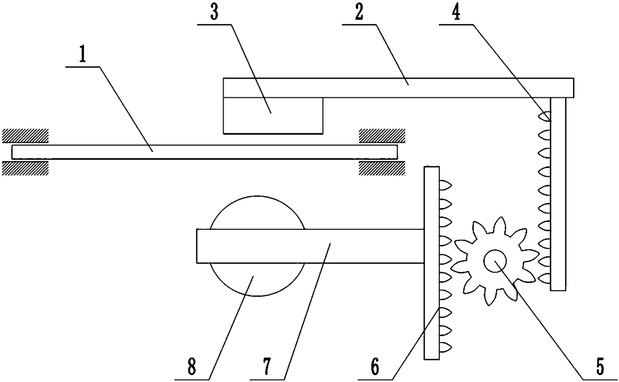
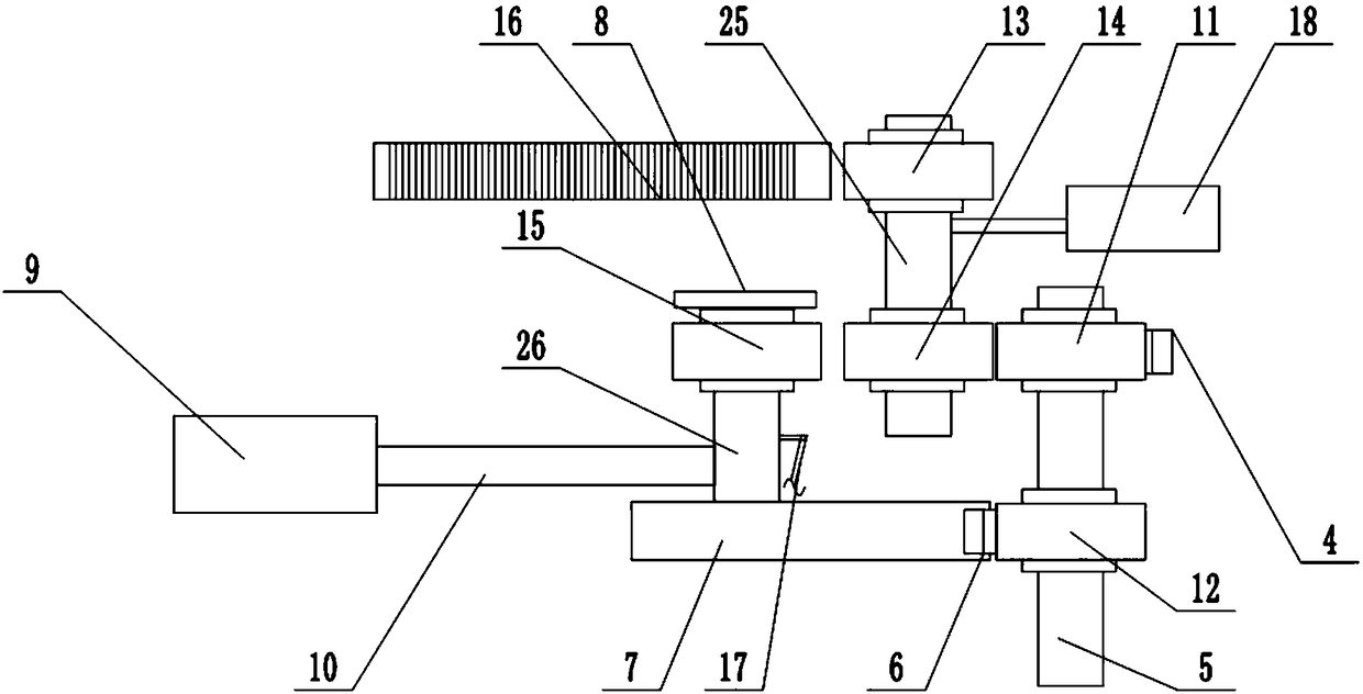
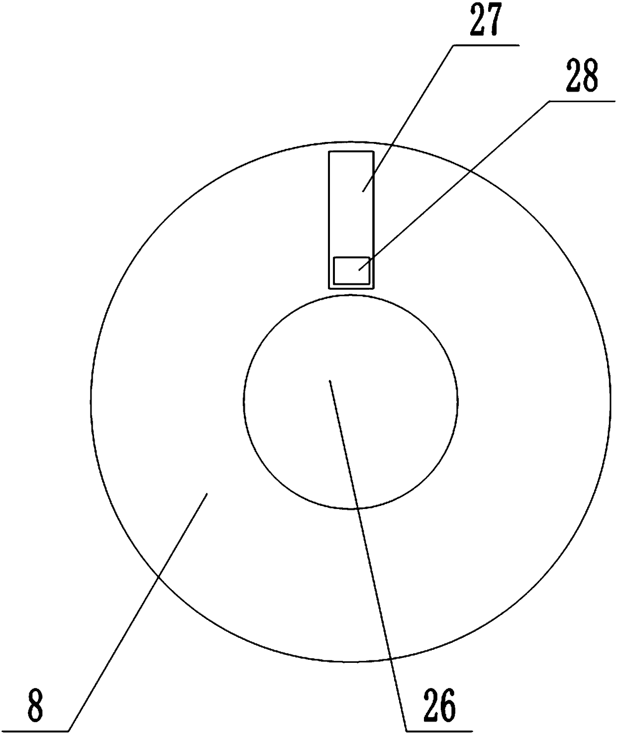
[0030] The reference signs in the drawings of the description include: workbench 1, connecting rod 2, pressure plate 3, third rack 4, second rotating shaft 5, second rack 6, cutting seat 7, circular saw blade 8, piston barrel 9. Piston rod 10, third gear 11, second gear 12, first gear 13, driving gear 14, driven gear 15, first rack 16, pole 17, cylinder 18, first push rod 19, the first Two push rods 20, first spring 21, second spring 22, third push rod 23, third spring 24, first rotating shaft 25, cutting shaft 26, chute 27, slide block 28.

[0031] Such as figure 1 As shown, the plate grooving device includes a frame, on which a workbench 1 is fixedly connected, and a transverse cutting seam is arranged on the workbench 1, and a connecting rod 2 is arranged on the frame above the workbench 1, and the connecting rod 2 The left end of the connecting rod 2 is fixedly connected with a...


PUM


Abstract

The invention belongs to the panel grooving device, and in particular relates to a panel grooving device. The panel grooving device comprises a rack, wherein a worktable is arranged on the rack; a cutting slit is formed in the worktable; a cutting shaft, a first rotary shaft and a second rotary shaft are successively arranged from left to right below the worktable; a first gear and a driving gearare arranged on the first rotary shaft; a first rack parallel to the direction of the cutting slit and engaged to the first gear is fixedly connected to the rack; an air cylinder is also arranged on the right side of the first rotary shaft on the rack; and a push rod of the air cylinder leans against the first rotary shaft; a disc saw web is arranged right below the cutting slit on the cutting shaft; and a second gear engaged to the second rack is arranged on the second rotary shaft. By adopting the scheme, the demand of compressing the panel is met during grooving, and the grooving precisionis ensured.

Description

technical field [0001] The invention belongs to the field of decoration design, and in particular relates to a plate groove cutting device. Background technique [0002] In architectural decoration projects, it is usually necessary to use a lot of decorations made of PVC boards, acrylic boards and other materials. In the process of making these decorations, it is often necessary to bend the boards. Due to the poor plasticity of PVC and other materials, direct bending It is easy to crack the sheet, so the inside of the bend is usually notched first, and then bent. Among them, the depth and uniformity of the grooving have high requirements, otherwise the bending effect and service life will be affected. [0003] The prior art grooving machine includes a workbench, on which a cutting slit is arranged, and a cutter is fixed above the workbench. When in use, the plate is placed on the workbench, and the plate is pushed through the cutter. The cutting force of the cutter Cut gro...

Claims


Application Information

Patent Timeline
IPC IPC(8): B26D3/06B26D1/18B26D5/08B26D5/02B26D7/02B26D7/18B26D7/26
CPCB26D3/06B26D1/18B26D5/02B26D5/08B26D7/02B26D7/1863B26D7/2635
Inventor 范宏伟
Owner 重庆鸥能建筑劳务有限公司
Why Eureka
Try Eureka