Uplift pile side post grouting device and construction method

A technology of anti-pull piles and grouting devices, which is applied to sheet pile walls, foundation structure engineering, construction, etc., can solve the problem of affecting the grouting bonding area of ​​the pile side, the difficulty of inserting the grouting core pipe, and the difficulty of inserting and pulling out. and other problems, to achieve the effect of eliminating dredging, reducing labor costs, and smooth grouting process

Pending Publication Date: 2018-09-04
NINGBO HONGCHEN CONSTR
View PDF5 Cites 5 Cited by
  • Summary
  • Abstract
  • Description
  • Claims
  • Application Information

AI Technical Summary

Problems solved by technology

The post-grouting device and construction method of the prior art above have the following disadvantages: 1. The grout sprayed from the conduit grouting nozzle is often on the local pile side, which cannot be evenly distributed around the pile side, thereby affecting the pile side. Bonding area of ​​grouting
2. After the first pressure grouting, the grout remains in the conduit, which affects the insertion and grouting of the grouting core pipe again or again, that is, it is very difficult to continue to insert the grouting core pipe
3. When the pile length is very long, such as 60 meters, there are many grouting sections on the pile side, and the grouting core pipe is thin and long. Insertion and extraction are affected by deformation and become difficult, that is, the construction efficiency is low
In particular, due to various reasons, the post-grouting of the side of the uplift pile in the prior art is constructed on a level-by-level level, and at the same time, in order to avoid the mutual interference and influence of the post-grouting liquid on the side of the adjacent upper and lower level piles, After the post-grouting of the pile side of one elevation is completed, the post-grouting of the pile side of the second elevation is generally waited for 2 hours. More than 18 hours, the construction time is long, the construction efficiency is low, and so far, the technical problems that plague this technical field have not been solved

Method used


Image

  • Uplift pile side post grouting device and construction method
  • Uplift pile side post grouting device and construction method
  • Uplift pile side post grouting device and construction method

Examples


Embodiment Construction

[0034] The specific embodiments of the present invention will be further described below in conjunction with the accompanying drawings. What needs to be declared here is that the descriptions of these embodiments are used to help understand the present invention, but are not intended to limit the present invention. In addition, the technical features and technical means involved in the various embodiments of the present invention described below may be combined with each other as long as they do not constitute a conflict with each other.

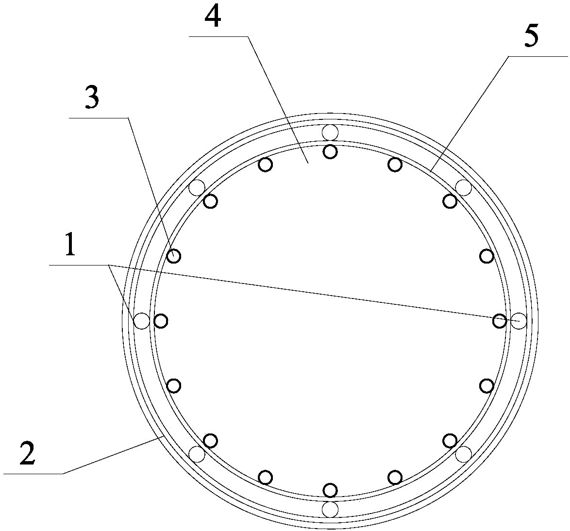
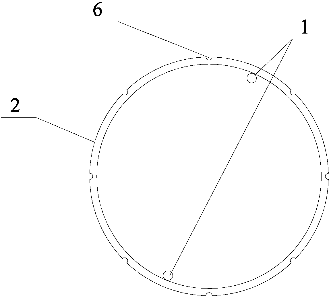
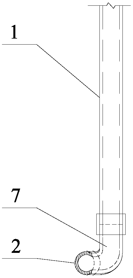
[0035] like figure 1 , figure 2 , image 3 , Figure 4 , Figure 7 shown

[0036] Post grouting device for uplift pile side of the present invention, the uplift pile here is also the uplift bored pile, the pile side refers to the circumferential side of the pile, and the back grouting refers to the pile body concrete 4 to be poured by the uplift pile. Grouting after predetermined strength.

[0037] Post-grouting device for uplift pil...


PUM


Abstract

The invention discloses an uplift pile side post grouting device. The uplift pile side post grouting device comprises a plurality of grouting vertical tubes and a plurality of grouting ring tubes withdifferent elevations, wherein the grouting vertical tubes are fixed on the periphery of an uplift pile reinforcement cage; the grouting ring tubes are connected with the grouting vertical tubes and are fixed on the outer sides of the grouting vertical tubes; the bottom ends of each two grouting vertical tubes communicate with one corresponding grouting ring tube; a plurality of slurry outlet nozzles are arranged on each grouting ring tube along the periphery; and each slurry outlet nozzle can be temporarily closed by a closing device which can be flushed away by water pumped in by a water pump. A construction method of the uplift pile side post grouting device comprises the following steps: fixing the prefabricated grouting vertical tubes and the prefabricated grouting ring tubes on a pile body reinforcement cage; temporarily closing the slurry outlet nozzles on the grouting ring tubes by wrapping adhesive tapes or one-way valves, wherein each one-way valve is connected with water-permeable and slurry-tight slurry bags at intervals in a sealed manner; and unplugging the grouting vertical tubes and the grouting ring tubes by high-pressure water and completing pile side post grouting in twice or at a time. By the device and method, post grouting on the side surfaces of the peripheries of uplift piles can be uniformly distributed along the peripheries, grouting is smooth, and theconstruction efficiency is high.

Description

technical field [0001] The invention relates to the technical field of civil engineering construction, in particular to a post-grouting device and a construction method for post-grouting the side of the uplift bored cast-in-situ pile, that is, the circumferential side of the pile. Background technique [0002] In my country's river and coastal areas, the groundwater is abundant and the water level is usually buried 1-3m below the surface. With the development of underground space to deep and large-scale development, the anti-floating problem of underground space engineering under the action of groundwater is becoming more and more prominent. From the anti-floating technology of underground space engineering, there are generally methods such as increasing the self-weight of the underground space structure, increasing the weight of the covering soil on the roof of the basement, and setting uplift anchors or uplift piles. Setting uplift-resistant bored piles is the most commonl...

Claims


Application Information

Patent Timeline
Patent Type & Authority Applications(China)
IPC IPC(8): E02D15/04E02D5/34
CPCE02D5/34E02D15/04E02D2250/003
Inventor 李福连李连方尚伟徐和星蒋光松
Owner NINGBO HONGCHEN CONSTR
Why Eureka
Try Eureka