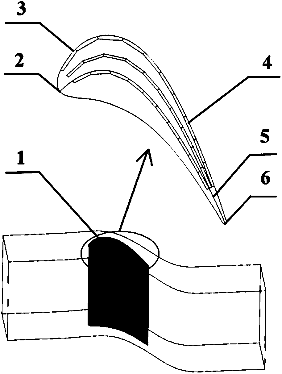
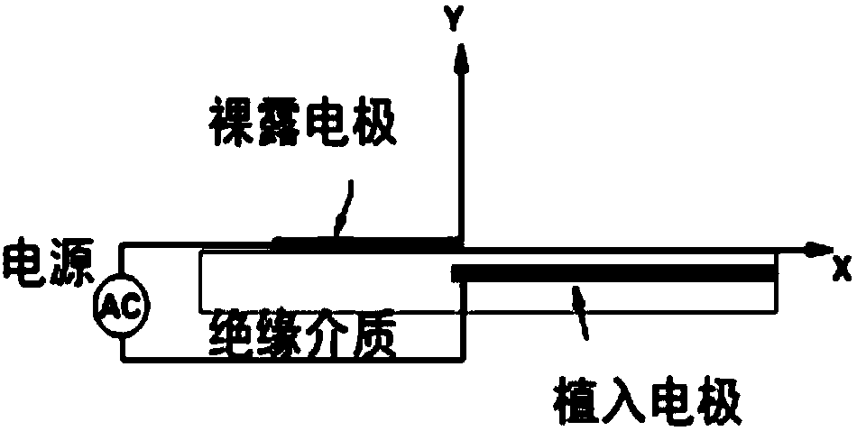
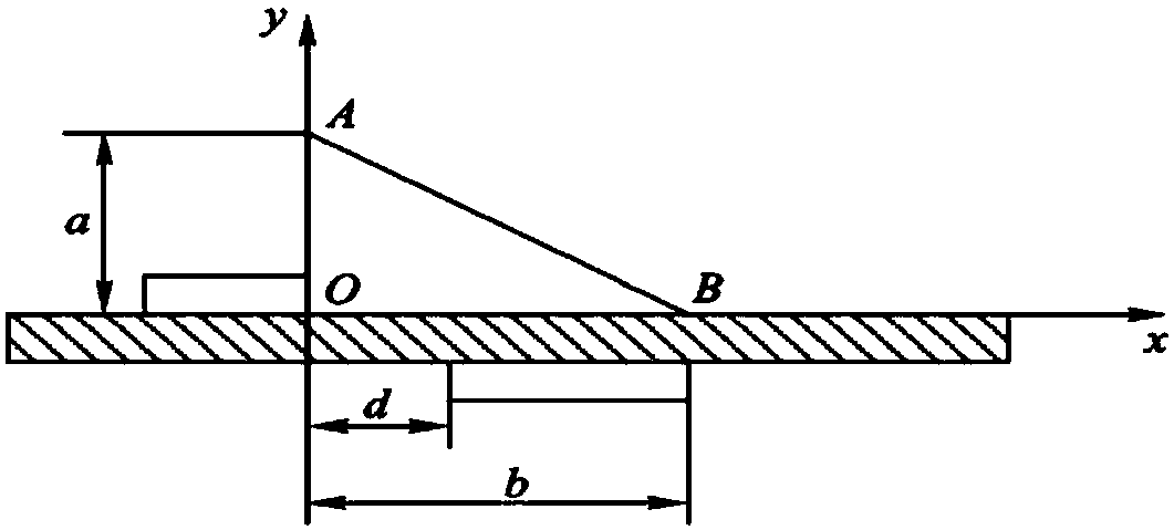
Turbine cascade blade top structure with array type DBD plasma excitation layout

An array type, plasma technology, applied in the direction of blade support components, engine components, machines/engines, etc., can solve the problems of energy leakage and loss at the top of the blade, and achieve the goal of suppressing leakage flow, reducing leakage flow and energy loss coefficient Effect

Inactive Publication Date: 2018-09-04
HARBIN INST OF TECH
View PDF8 Cites 0 Cited by
  • Summary
  • Abstract
  • Description
  • Claims
  • Application Information

AI Technical Summary

Problems solved by technology

[0005] The purpose of the present invention is to solve the problem of energy loss caused by the leakage flow formed on the top of the blade due to the pressure diffe

Method used


Image

  • Turbine cascade blade top structure with array type DBD plasma excitation layout
  • Turbine cascade blade top structure with array type DBD plasma excitation layout
  • Turbine cascade blade top structure with array type DBD plasma excitation layout

Examples


specific Embodiment

[0030] In order to verify the effect of the present invention, carry out following numerical simulation, concrete simulation parameter and result are as follows:

[0031] The main parameters of the simulated turbine cascade profile are shown in Table 1:

[0032] Table 1

[0033]

[0034] Such as Figure 5 As shown, the size of the leakage vortex is significantly reduced when the array plasma excitation scheme is applied compared with the non-array plasma excitation scheme. Therefore, it shows that the scheme of the present invention can effectively control the flow in the tip clearance and reduce the leakage flow.

[0035] Such as Figure 6 It can be seen from the results of the leakage flow and energy loss coefficient of the numerical simulation that the leakage flow is reduced by 45.2% when the array plasma excitation scheme is applied compared with the non-array plasma excitation scheme. The energy loss coefficient decreased by 21.6%.

[0036] It can be seen that, b...


PUM


Abstract

The invention discloses a turbine cascade blade top structure with an array type DBD plasma excitation layout and belongs to the technical field of turbine active control. The problem that due to theeffects of the two side pressure differential of the pressure face and the suction face of a blade, energy loss is caused by leakage flowing formed at the blade top can be solved. The turbine cascadeblade top structure comprises a blade top and a plurality of plasma exciters. The multiple plasma exciters are arranged on a plurality of contour lines on the upper surface of the blade top in an array mode. The contour lines are lines formed from the front edge point of the blade top to the tail edge point. The length direction of a bare electrode of the plasma exciter on each contour line is parallel to the corresponding contour line, and the length of the bare electrode on each contour line is smaller than or equal to the length of the corresponding contour line. The turbine cascade blade top structure is an active flowing control blade top structure.

Description

technical field [0001] The invention relates to a turbine blade cascade blade top structure with an array type DBD plasma excitation layout, and belongs to the technical field of turbine active control. Background technique [0002] Due to the inevitability of the gap between the blade top of the turbine cascade and the casing, under the action of the pressure difference between the pressure side and the suction side of the blade, the top of the moving blade will form a leakage flow from the pressure side to the suction side. Leakage flow will not only reduce the flow rate of working fluid and aerodynamic load, but also cause greater shear loss and mixing loss. Therefore, the research on the tip clearance leakage flow has always been one of the research focuses in the field of turbomachinery. [0003] At present, the research on interstitial flow control is divided into active control and passive control. Among them, the active control is to consider the injection of airfl...

Claims


Application Information

Patent Timeline
IPC IPC(8): F01D5/14
CPCF01D5/141F01D5/147
Inventor 俞建阳陈浮王钊
Owner HARBIN INST OF TECH
Why Eureka
Try Eureka