Supercharge Your Innovation With Domain-Expert AI Agents!

Gas synergistic power generation system based on industrial dragging

A technology of power generation system and power generation subsystem, which is applied in steam generation, liquid degassing, machine/engine, etc., can solve the problems of underutilization of by-product gas resources in factories, insufficient utilization of heat energy of by-product gas, and low thermal efficiency. , to achieve the effect of lowering the elevation of the main plant, reducing condensing equipment and pipes, and improving thermal efficiency

Active Publication Date: 2018-09-04
HUATIAN ENG & TECH CORP MCC
View PDF3 Cites 0 Cited by
  • Summary
  • Abstract
  • Description
  • Claims
  • Application Information

AI Technical Summary

Problems solved by technology

However, both low-parameter boilers and low-parameter steam turbines have disadvantages such as low efficiency and high heat consumption, which leads to the underutilization of by-product gas resources in the factory
For example, a steel plant has successively built more than ten medium-temperature and medium-pressure steam turbines, and the steam is supplied by multiple medium-temperature and medium-pressure gas boilers. The actual operating efficiency of these medium-temperature, medium-pressure and small-capacity boilers is only 82%, which is far lower than that of high-parameter large-capacity boilers. In addition, the efficiency of medium-temperature and medium-pressure steam turbines is much lower than that of high-parameter steam turbines, which leads to low thermal efficiency of the whole plant and a serious shortage of thermal energy utilization of by-product gas

Method used


Image

  • Gas synergistic power generation system based on industrial dragging

Examples


Embodiment Construction

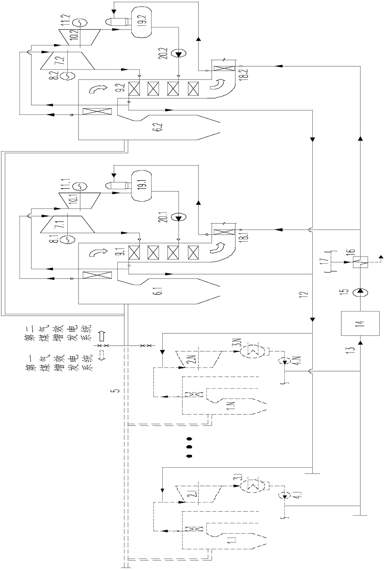
[0023]The following will describe the embodiment of the gas efficiency power generation system based on industrial drive according to the present invention with reference to the accompanying drawings. Those skilled in the art would recognize that the described embodiments can be modified in various ways or combinations thereof without departing from the spirit and scope of the invention. Accordingly, the drawings and description are illustrative in nature and not intended to limit the scope of the claims. Also, in this specification, the drawings are not drawn to scale, and like reference numerals denote like parts.

[0024] In the industrial drag-based gas efficiency power generation system of the present invention, the low parameters and high parameters refer to the comparison between the first gas efficiency power generation system and the second gas efficiency power generation system. Wherein the parameters refer to performance parameters such as pressure and temperature....


PUM


Abstract

A gas synergistic power generation system based on industrial dragging comprises a gas pipe network, a first gas synergistic power generation system body and a second gas synergistic power generationsystem body. The first gas synergistic power generation system body comprises a low-parameter gas boiler and a low-parameter gas turbine. The second gas synergistic power generation system body comprises a plurality of second gas synergistic power generation subsystems. Each second gas synergistic power generation subsystem comprises a high-parameter gas boiler, a high-parameter first turbine, a high-parameter second turbine, a high-parameter first generator, a high-parameter second generator and a deaerator. In the first gas synergistic power generation system body, the steam generated by thelow-parameter gas boiler drives the low-parameter turbine to do work. In each second gas synergistic power generation subsystem, the steam generated by the high-parameter gas boiler sequentially enters the high-parameter first turbine and the high-parameter second turbine to drive the corresponding generators to generate power.

Description

technical field [0001] The invention relates to the technical field of high-efficiency utilization of energy, in particular to a gas efficiency power generation system based on industrial traction. Background technique [0002] In the production processes of iron and steel, coking and other fields, there are a large number of high-power and high-energy-consuming rotating machines, including fans, compressors, water pumps, etc., as auxiliary facilities for process equipment. main factor. On the other hand, by-product gas, such as blast furnace gas, converter gas, coke oven gas, etc., will be produced in the process of iron and steel and coking production. In recent years, with the improvement of awareness of energy conservation and emission reduction in various factories and the improvement of technical capabilities, a large number of factories have adopted steam turbine drive instead of traditional motor drive to drive these high-power rotating machines and send the above-m...

Claims


Application Information

Patent Timeline
Patent Type & Authority Applications(China)
IPC IPC(8): F01K11/02F01K23/10F01D15/10F22D1/02F22D11/06F22D1/50F22G7/12F23K5/00
CPCF01D15/10F01K11/02F01K23/10F22D1/02F22D1/50F22D11/06F22G7/12F23K5/005
Inventor 江文豪
Owner HUATIAN ENG & TECH CORP MCC
Features
  • R&D
  • Intellectual Property
  • Life Sciences
  • Materials
  • Tech Scout
  • Unparalleled Data Quality
  • Higher Quality Content
  • 60% Fewer Hallucinations
Learn More