Split type calibration target, calibration device with same and calibration method thereof

A calibration device and a separate technology, applied in the field of calibration targets, can solve the problems of difficult concentricity of the pyramid mirror and the hemisphere, and achieve the effects of precise positioning and high repeatability.

Pending Publication Date: 2018-09-04
SHANGHAI INST OF MEASUREMENT & TESTING TECH
View PDF10 Cites 27 Cited by
  • Summary
  • Abstract
  • Description
  • Claims
  • Application Information

AI Technical Summary

Problems solved by technology

But this method, firstly, the sphericity accuracy of the hemisphere will not be very high, and secondly, it is difficult to ensure th

Method used


Image

  • Split type calibration target, calibration device with same and calibration method thereof
  • Split type calibration target, calibration device with same and calibration method thereof

Examples


Embodiment Construction

[0023] In order to make the technical means, creative features, goals and effects achieved by the present invention easy to understand, the split calibration target of the present invention and the calibration device with the split calibration target and the use of the calibration device will be described below in conjunction with the accompanying drawings and embodiments The calibration method for calibrating the laser scanner is described in detail.

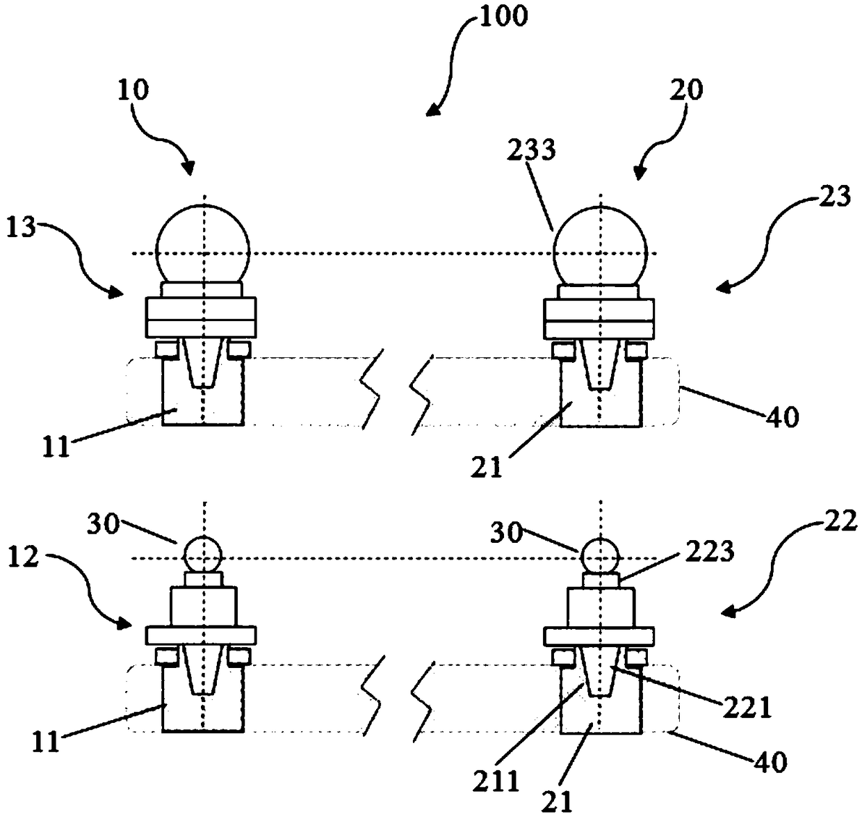
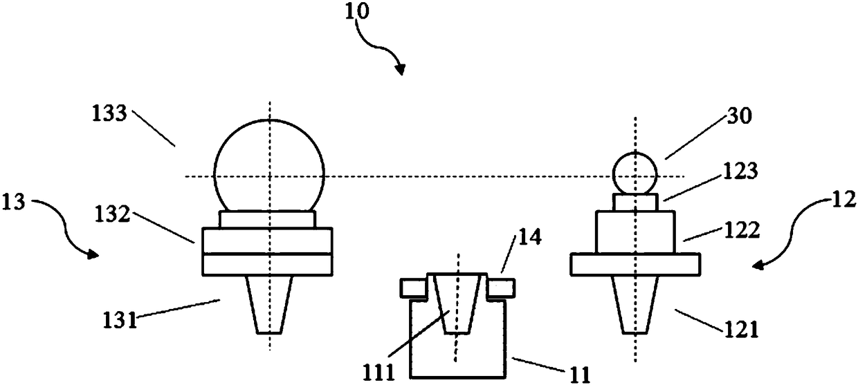
[0024] figure 1 It is a structural schematic diagram of the calibration device in the embodiment of the present invention.

[0025] Such as figure 1 As shown, the calibration device 100 is used to measure the spatial distance indication error of the laser scanner, including a first split calibration target 10, a second split calibration target 20, a target mirror 30, a length connector 40, a laser tracker (Fig. not shown in ). The structure of the first split calibration target 10 is the same as that of the second split cali...


PUM


Abstract

The invention provides a split type calibration target which cooperates with a target lens to be used as a measurement target when a laser tracker is utilized for calibrating a spatial distance indication error of a laser scanner. The split type calibration target comprises a target seat, a target lens bearing component and a sphere target component, wherein the target lens bearing component is provided with a taper shank, a connecting piece arranged on the taper shank and a target lens seat which is arranged on the connecting piece and used for being connected with the target lens through magnetic adsorption; and the sphere target component is provided with a sphere side taper shank, a three-dimensional regulating mechanism arranged on the sphere side taper shank and a sphere target arranged on the three-dimensional regulating mechanism, wherein the taper shank and the sphere side taper shank are morse taper shanks respectively, the morse taper shanks have the same size and tolerance,taper tips are arranged downward, a morse taper sleeve is arranged on the target seat, the taper tip of the morse taper sleeve is downward, an opening is upward, and the morse taper sleeve is matchedwith the taper shank and the sphere side taper shank. The invention also provides a calibration device provided with the split type calibration target and a method for calibrating the laser scanner by utilizing the calibration device.

Description

technical field [0001] The invention relates to a calibration target, in particular to a split calibration target, a calibration device with the split calibration target, and a calibration method for calibrating a laser scanner by using the calibration device. Background technique [0002] With the development of science and technology, especially major projects such as large aircraft manufacturing, there are more and more demands for digital precise positioning and assembly, accurate three-dimensional measurement of large parts, product quality monitoring and reverse engineering, laser tracker, laser radar, Laser 3D scanners, iGPS and other new space coordinate measuring instruments are more and more widely used. The spatial ranging accuracy of such instruments is the premise of the processing accuracy of large parts and the assembly accuracy of large equipment such as automobiles, airplanes, and fans. [0003] The emergence and development of 3D laser measurement technolo...

Claims


Application Information

Patent Timeline
IPC IPC(8): G01B11/00G01B11/02
CPCG01B11/002G01B11/03
Inventor 刘芳芳任瑜马建敏张波傅云霞雷李华
Owner SHANGHAI INST OF MEASUREMENT & TESTING TECH
Why Eureka
Try Eureka