
Space charge measurement device and measurement method suitable for interface effect research

A space charge and interface effect technology, applied in the direction of measuring devices, measuring electrical variables, instruments, etc., can solve problems such as lack of impact mechanism, achieve the effect of ensuring work stability, easy operation, and accurate measurement

Active Publication Date: 2020-08-18
XI AN JIAOTONG UNIV +1
View PDF11 Cites 0 Cited by
  • Summary
  • Abstract
  • Description
  • Claims
  • Application Information

AI Technical Summary

Problems solved by technology

However, there is still a lack of in-depth research on the mechanism of the interface effect on space charge injection at high temperatures; on the other hand, there are few reports on the use of electrode surface treatment to suppress space charge injection.

Method used


Image

  • Space charge measurement device and measurement method suitable for interface effect research

Examples


Embodiment 1

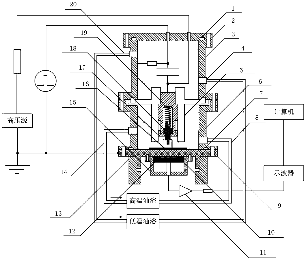
[0031] The present invention is applicable to the space charge testing method of interface effect research, comprises the following steps:

[0032] 1) According to the degree of close contact between the sample and the upper electrode required for the test, select a spring with a suitable wire diameter and length and place it inside the electrode barrel, press the upper electrode seat on the lower part of the spring, and screw the electrode cap 17 to the electrode barrel 19 superior;

[0033] 2) Insert the assembled spring electrode into the inside of the PTFE separator 5, and fix the hexagonal screws through the two through holes on the side of the PTFE separator 5 to the two threaded holes on the side of the electrode cylinder 19, which can effectively Prevent the rotation of the electrode cylinder 19 inside the PTFE separator 5, and fix the PTFE separator 5 and the shell of the pulse coupling circuit cavity 3 together by hexagonal screws;

[0034] 3) Screw the upper electr...

Embodiment 2

[0041] The difference between this embodiment and embodiment 1 is only:

[0042] During the measurement process, according to the tightness of contact between the sample and the upper electrode 16 required for the test, that is, the force exerted by the upper electrode on the sample, the wire diameter and length of the spring in step 1) are changed to achieve different pressures and different temperature conditions Under the space charge test.

Embodiment 3

[0044] The difference between this embodiment and embodiment 1 is only:

[0045] In the measurement process, if it is necessary to study the influence of different electrode materials on space charge injection, unscrew the original upper electrode 16 in step 3), and screw on the required test electrode, so that space charge injection can be achieved when the electrode materials are different. characteristic tests.


PUM


Abstract

The invention provides a space charge measuring device suitable for interface effect research and a measuring method thereof. The measuring device successively comprises a pulse coupling circuit cavity, a test cavity and a base from top to bottom. A pulse coupling circuit connected with an external high voltage source and a pulse source is arranged in the pulse coupling circuit cavity. The sidewall of the pulse coupling circuit cavity is provided with a hole and is connected with a normal temperature oil bath pipeline. The sidewall of the test cavity is provided with a hole and is connected with a high temperature oil bath pipeline. The measuring method comprises the steps that according to the required contact closeness between a sample and an upper electrode, a corresponding spring is taken into a spring cavity; the spring is pushed by an electrode seat; the upper electrode required for a test is arranged on an upper electrode seat; the sample is placed at the center of the upper surface of a lower electrode, so that the upper electrode can press the sample without gap between the upper electrode and the sample; and after a temperature sensor reaches a set value and is stabilized, space charge measuring of the sample at that temperature is carried out. According to the invention, accurate measurement of space charge injection characteristics under different electrode surfaceconditions is realized.

Description

technical field [0001] The invention belongs to the field of electrical insulation testing, and relates to a space charge measurement device and a measurement method suitable for interface effect research, which can be used to study the space charge injection characteristics of solid insulating materials under different interface conditions. Background technique [0002] During the operation of UHV DC equipment, the central conductor has a large carrying capacity, high equipment temperature and high electric field strength at key positions. The central conductor injects a large amount of space charge into the insulating material, which distorts the internal electric field distribution of the equipment, which will accelerate the insulating material. aging, and reduce the discharge initiation threshold field strength, affecting the life and stability of UHV DC equipment. [0003] It is necessary to study the relationship between the interface effect and the space charge inject...

Claims


Application Information

Patent Timeline
Patent Type & Authority Patents(China)
IPC IPC(8): G01R29/24
CPCG01R29/24
Inventor 刘鹏张丝钰苏夏霖莫云浩闫家启张宏亮彭宗仁
Owner XI AN JIAOTONG UNIV
Learn More