Electrical connector and terminal

An electrical connector and electrical connection technology, which is applied in the direction of connection and connection device parts, circuits, etc., can solve the problems of disengagement between the contact part and the conductive sheet, large contact area between the contact part and the chip module, and non-conduction. , to achieve the effect of ensuring stable contact, reducing the risk of non-conduction, and small contact area

Active Publication Date: 2018-09-04
DEYI PRECISION ELECTRONIC IND CO LTD PANYU
View PDF7 Cites 5 Cited by
  • Summary
  • Abstract
  • Description
  • Claims
  • Application Information

AI Technical Summary

Problems solved by technology

[0003] However, this electrical connector has at least the following disadvantages: due to the manufacturing tolerances of the chip module, there is a height difference in the circular conductive sheet located on the bottom surface of the chip module, so that part of the conductive sheet is higher than other surrounding components, and the contact portion and the chip module The contact area is large, and the height of the contact part is consistent from the inside to the outside. When the chip module presses down on the terminal, the outer side of the contact part is far away from the center of the conductive sheet, so it is easy to slide out of the conductive sheet of the chip module and contact with the conductive sheet. Other components on the chip module that are lower than the conductive sheet are in contact, causing the contact part to be out of contact with the conductive sheet, causing the conductive terminal to be disconnected from the chip module

Method used


Image

  • Electrical connector and terminal
  • Electrical connector and terminal
  • Electrical connector and terminal

Examples


Embodiment Construction

[0056] In order to facilitate a better understanding of the purpose, structure, features, and effects of the present invention, the present invention will now be further described with reference to the drawings and specific embodiments.

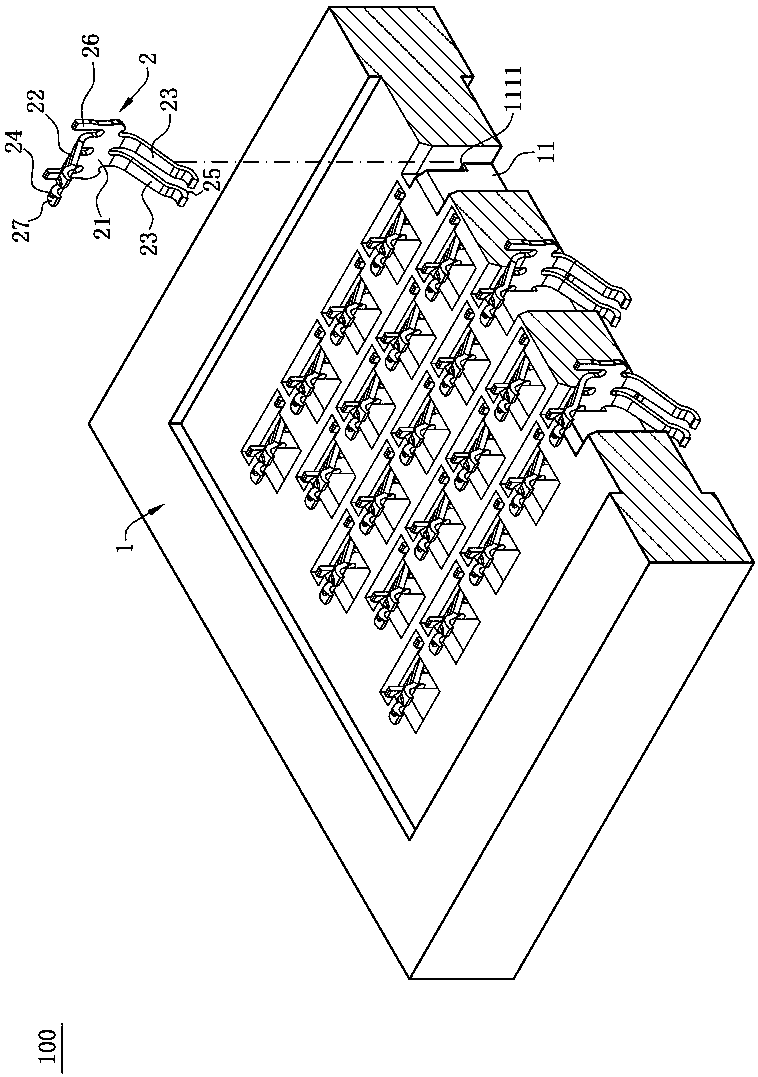
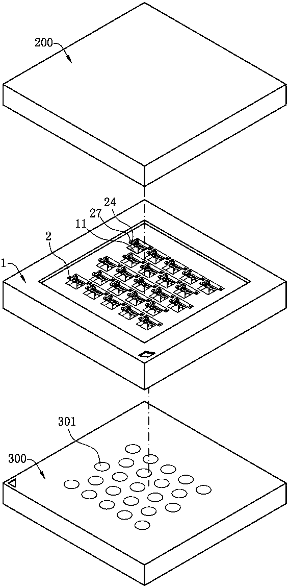
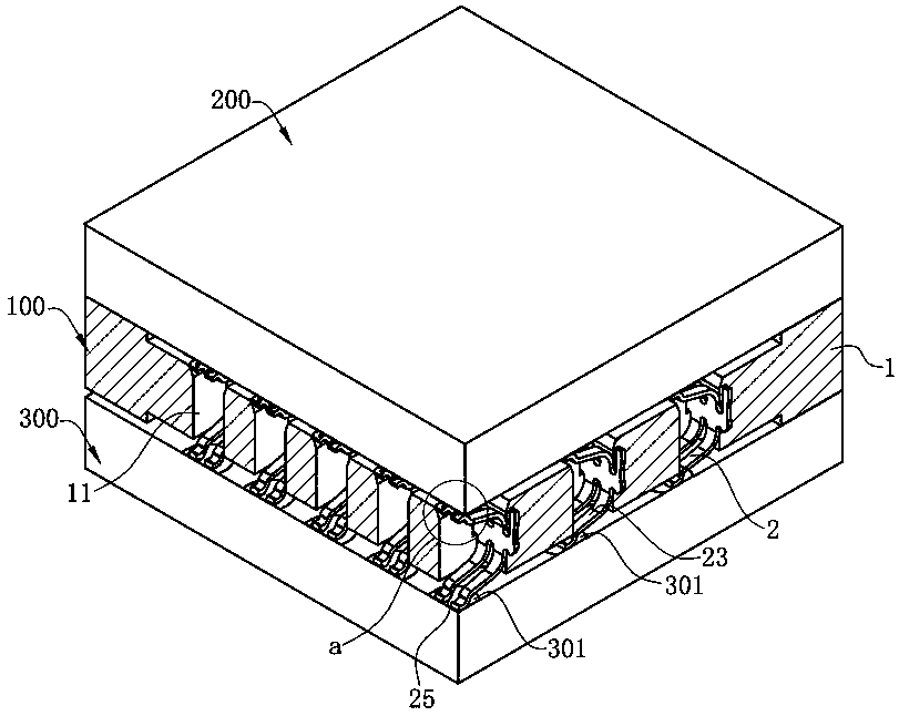
[0057] Such as Figure 1 to Figure 11 Shown here is the first embodiment of the electrical connector 100 of the present invention, which is used to electrically connect a chip module 200 to a circuit board 300. It includes an insulating body 1 and a plurality of Terminal 2.

[0058] Such as figure 1 with Figure 8 As shown, the insulating body 1 has a plurality of receiving holes 11 passing through the insulating body 1 up and down, the receiving holes 11 are arranged in a row and staggered, and each of the receiving holes 11 is recessed with a clamping groove 111 on opposite sides. Each of the retaining grooves 111 has a blocking surface 1111.

[0059] The plurality of the terminals 2 are correspondingly received in the plurality of the receiving ...


PUM


Abstract

The invention discloses a connector which comprises an insulation body provided with a slot, and a first pair of terminals and a second pair of terminals arranged on the insulation body, the first pair of terminals and the second pair of terminals which are arranged in a staggered mode are distributed on the same side of the slot in the lengthwise direction, the two first welding parts in the first pair of terminals are deviated from the two first contact parts in opposite directions in the lengthwise direction, and the two second welding parts in the second pair of terminals are deviated fromthe two second contact parts in opposite directions in the lengthwise direction, the first welding parts of the first pair of terminals and the first welding parts of the second pair of terminals aredistributed on opposite sides of the first body parts of the first pair of terminals in the transverse direction, and distributed on the two opposite sides of the second body parts of the second pairof terminals. The staggered arrangement of the paired terminals is facilitated, and the distribution of the conductive holes of the corresponding paired terminals on the circuit board is facilitated,short circuits are not easy to cause, and distribution of multiple types of terminals is facilitated, so that the connector has good electrical performance in the transmission process.

Description

Technical field [0001] The invention relates to an electrical connector and terminal, in particular to a planar grid array electrical connector and terminal for electrically connecting a chip module to a circuit board. Background technique [0002] The Chinese patent with the patent number 200420054523.6 discloses an electrical connector, which includes an insulating body provided with a receiving hole, and conductive terminals received in the receiving hole to connect the chip module and the circuit board. It mainly includes a main body and a main body The upper and lower sides of the upper and lower sides are provided with obliquely extending arm portions. The end of the arm portion is provided with a contact portion that is connected to the electronic component. At least two arm portions are provided on at least one side of the main body portion to ensure that the electrical connector terminal and the chip module or Better electrical conduction performance between circuit boar...

Claims


Application Information

Patent Timeline
Patent Type & Authority Applications(China)
IPC IPC(8): H01R12/71H01R13/24H01R33/74
CPCH01R12/714H01R12/716H01R13/2414H01R13/2435H01R13/2457H01R13/2492H01R33/74H01R12/7076
Inventor 朱德祥
Owner DEYI PRECISION ELECTRONIC IND CO LTD PANYU
Why Eureka
Try Eureka