
A double-sided adhesive die-cutting waste discharge mechanism for a die-cutting machine and its working method

A technology of double-sided tape and die-cutting machine, which is used in metal processing, thin material processing, sending objects, etc. problems such as secondary utilization, to achieve the effect of improving convenience, reducing space occupied, and improving processing capacity

Active Publication Date: 2022-04-01
深圳市兴龙宝实业有限公司
View PDF14 Cites 0 Cited by
  • Summary
  • Abstract
  • Description
  • Claims
  • Application Information

AI Technical Summary

Problems solved by technology

[0003] However, the existing waste discharge mechanism has great problems during use. The existing waste discharge mechanism will affect the die-cutting speed of the double-sided adhesive die-cutting machine and reduce the production efficiency of the die-cutting machine. The existing waste discharge mechanism The components of the mechanism cannot be moved flexibly, which reduces the flexibility of use. The existing waste discharge mechanism directly sweeps the waste to the ground, which is easy to pollute the assembly and reduces the environmental protection of use. At the same time, the waste is not collected, so that The waste cannot be reused, which reduces the economic benefits of use

Method used


Image

  • A double-sided adhesive die-cutting waste discharge mechanism for a die-cutting machine and its working method
  • A double-sided adhesive die-cutting waste discharge mechanism for a die-cutting machine and its working method
  • A double-sided adhesive die-cutting waste discharge mechanism for a die-cutting machine and its working method

Examples


Embodiment Construction

[0034] In order to make the technical means, creative features, goals and effects achieved by the present invention easy to understand, the present invention will be further described below in conjunction with specific embodiments.

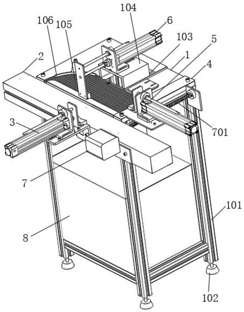
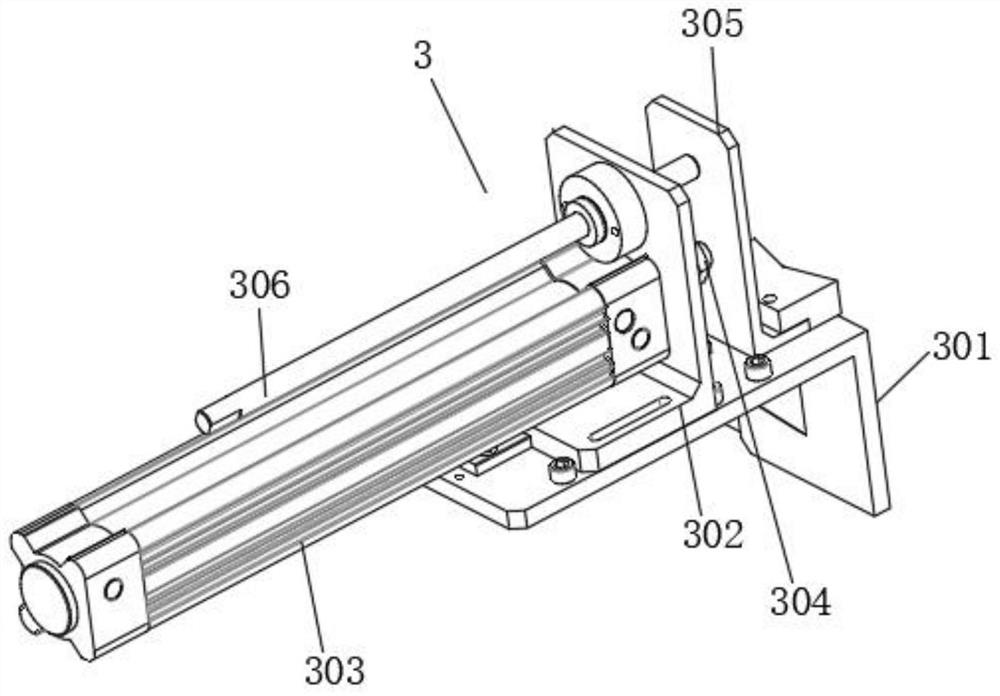
[0035] Such as Figure 1-Figure 7 As shown, a double-sided adhesive die-cutting waste discharge mechanism for a die-cutting machine according to the present invention includes an abutment 1, a fixed push assembly 3, a movable push assembly 5 and a discharge assembly 6, and a top of the abutment 1 The first connecting plate 2 is welded horizontally on the side, and the side of the first connecting plate 2 far away from the base 1 is installed with a fixed push assembly 3, and the end of the top of the base 1 is welded with a second connecting plate 4, and the second connecting plate 4 is far away from the base. One side of the platform 1 is slidably matched with a movable push assembly 5, and the top of the abutment 1 is respectively provided with ...


PUM


Abstract

The invention relates to the technical field of die-cutting machines, in particular to a double-sided adhesive die-cutting waste discharge mechanism for a die-cutting machine and its working method, which includes a base, a fixed push assembly, a movable push assembly and a discharge assembly. Driven by the second hydraulic cylinder, the die-cutting waste is compacted, thereby reducing the space occupied by the waste, thereby improving the processing capacity of the mechanism for the die-cutting waste. By using the motor to drive, the activity of the mechanism pushes the position of the component It can be adjusted, thereby making the use of the movable push component more flexible, thus improving the flexibility of the use of the double-sided adhesive die-cutting waste discharge mechanism. At the same time, by adjusting the position of the movable push component, the extrusion range of the movable push component can be The entire groove is covered to avoid extrusion dead angles, thereby improving the reliability of the waste discharge treatment of the mechanism and making the waste discharge of the mechanism more thorough.

Description

technical field [0001] The invention relates to the technical field of die-cutting machines, in particular to a double-sided adhesive die-cutting waste discharge mechanism for a die-cutting machine and a working method thereof. Background technique [0002] The working principle of the double-sided rubber die-cutting machine is to use a die-cutter, steel knife, metal mold, steel wire, etc. to apply a certain pressure through the embossing plate to cut the double-sided rubber into a certain shape, and then die-cut the double-sided rubber. During the working process of the machine, it is necessary to exclude the rest of the original products, which is referred to as waste discharge, and for the waste discharge of double-sided adhesive die-cutting, it is necessary to install a waste discharge mechanism in the double-sided adhesive die-cutting machine. [0003] However, the existing waste discharge mechanism has great problems during use. The existing waste discharge mechanism w...

Claims


Application Information

Patent Timeline
Patent Type & Authority Patents(China)
IPC IPC(8): B26D7/18B26D7/27B26D7/00B26F1/38B65H35/00
CPCB26D7/1818B26D7/27B26D7/00B26F1/38B65H35/0073B26D2007/0018
Inventor 孔飞盛富梅朱筱华
Owner 深圳市兴龙宝实业有限公司
Learn More