Sole sterilization drying unit

A drying unit and one-way valve technology, applied in the cleaning, chemical, and cleaning equipment of boots and shoes, can solve the problems of high manufacturing cost, cumbersome assembly process, lack of disinfection unit for shoe disinfection, etc., and achieve compact layout and simple structure , no power consumption effect

Pending Publication Date: 2018-09-07
CHONGQING JIEBANG ELECTRIC CO LTD
View PDF1 Cites 0 Cited by
  • Summary
  • Abstract
  • Description
  • Claims
  • Application Information

AI Technical Summary

Problems solved by technology

However, the splicing components of the cleaning machine are spliced ​​by dislocation and overlapping, which leads to the complex structure of the injection mold used for injection molding to form the skeleton, and has the defects of high manufacturing cost and cumbersome assembly process.
Also, the washer lacks a sanitizing unit for sanitizing shoes

Method used


Image

  • Sole sterilization drying unit
  • Sole sterilization drying unit
  • Sole sterilization drying unit

Examples


Embodiment 1

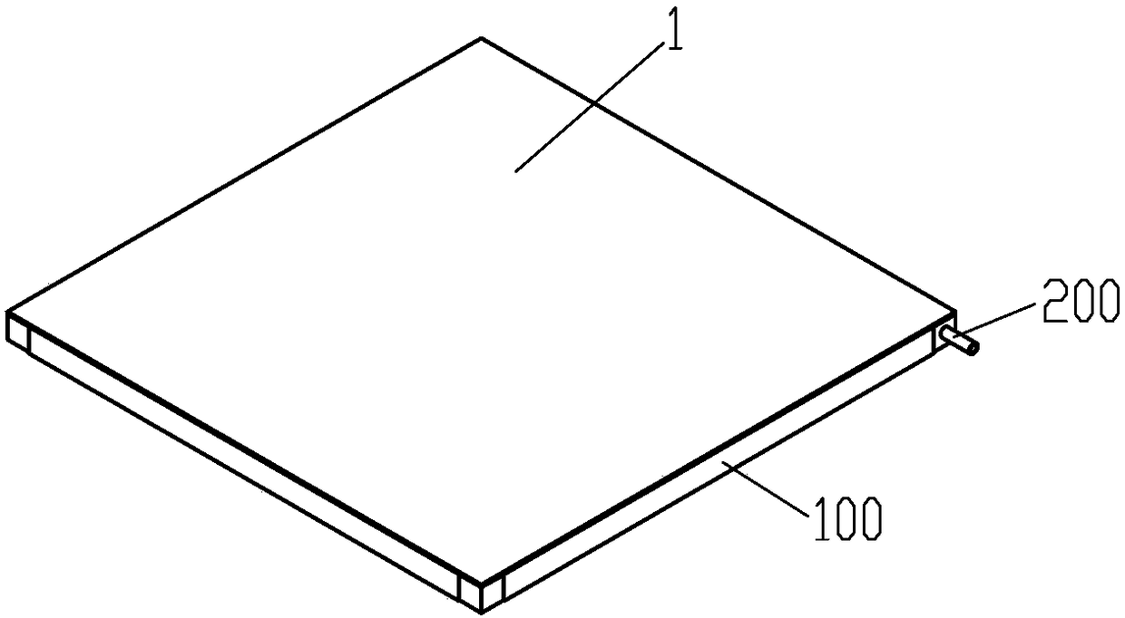
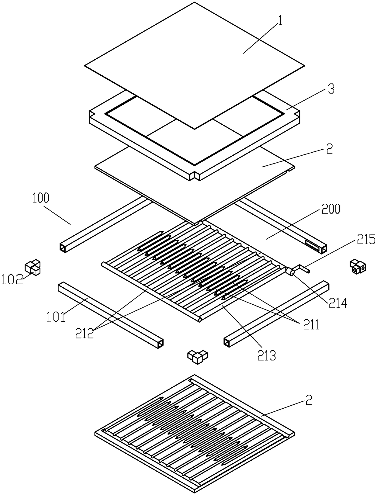
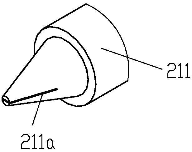
[0019] Example 1, see figure 1 , figure 2 , a shoe sole disinfection and drying unit, comprising a wiping surface layer 1 made of soft water-absorbing material, the wiping surface layer 1 is fixed on the upper surface of the surface layer fixing frame 100 through the periphery; the surface layer fixing frame 100 is provided with a disinfection humidification The device 200, the disinfecting and humidifying device 200 includes a plurality of liquid-feeding pipes 211 to form a liquid-feeding pipe row of a pipe structure. The liquid-feeding pipe row is made of soft elastic material. The liquid-feeding pipe 211 is horizontally suspended. The overhanging distal end constitutes the liquid outlet, and the liquid outlet has a one-way valve structure.

[0020] Wherein, the disinfection and humidification device 200 is provided with two oppositely arranged liquid feeding pipe rows, the liquid feeding pipe row includes a main pipe 212, and the two main pipes 212 are connected by a comm...

Embodiment 2

[0022] Example 2, see image 3 , a liquid discharge device 300 is provided below the disinfection and humidification device 200, the liquid discharge device has the same pipe structure as the disinfection and humidification device 200, and the discharge pipe 301 of the liquid discharge device is made of soft elastic material, and The bottom of the discharge pipe is closed, and there are multiple drainage inlet holes distributed on the pipe wall of the discharge pipe; a discharge check valve 302 is provided on the outlet section of the confluence main pipe of the two rows of discharge pipes, and the discharge pipes are wrapped In the two effusion sponges, the sponge pad 2 immediately above the drainage device 300 constitutes one of the effusion sponges, and the other effusion sponge is located below the drainage device 300. The groove in which the pipe row is embedded.

[0023] The rest of the structure of this embodiment is the same as that of Embodiment 1, and will not be re...


PUM


Abstract

The invention discloses a sole sterilization drying unit. The sole sterilization drying unit comprises a wiping surface layer made from a soft water absorbing material, wherein the wiping surface layer is fixed on the upper surface of a surface layer fixing frame through a periphery; the surface layer fixing frame is internally provided with a sterilization humidifying device, the sterilization humidifying device comprises a liquid adding pipe row with a rwo-pipe structure composed of a plurality of liquid adding pipes, the liquid adding pipe row is made from a soft elastic material, the liquid adding pipes horizontally overhang, overhanging distal ends of the liquid adding pipes compose liquid outlet ends, and the liquid outlet ends are one-way valve structures. The sole sterilization drying unit has the advantages that the humidification, sterilization and disinfection of the sole can be conveniently performed when the sole is wiped, the structure is simple, the layout is compact, nopower consumption exists, and the unit is energy saving and environmentally friendly.

Description

technical field [0001] The invention relates to shoe sole cleaning equipment, in particular to a shoe sole disinfection and drying unit. Background technique [0002] In indoor environments with high cleanliness requirements, it is usually necessary to put forward dust-free requirements for personnel entering the environment, such as changing special clothing and shoes before entering, or cleaning and dusting clothing, shoes and hats, etc. Especially some important laboratories, main workshops of electronic equipment factories, inspection and testing rooms of hospitals or factories, etc., all have increasingly stringent cleanliness requirements for indoor environments. The replacement of clothes and hats is relatively simple and convenient, and has strong versatility, and the hidden danger of disease transmission is small. However, the replacement of shoes seems troublesome and embarrassing, especially for the situation of outsiders, there is a hidden danger of foot disease...

Claims


Application Information

Patent Timeline
IPC IPC(8): A47L23/22A61L2/18
CPCA61L2/18A47L23/22
Inventor 李勇王瑶代雪峰
Owner CHONGQING JIEBANG ELECTRIC CO LTD
Why Eureka
Try Eureka