
Pouring flue gas dust removal process for continuous casting big ladles

A flue gas and continuous casting technology, applied in the field of metallurgy, can solve problems such as low flue gas capture rate, damage to the workshop environment, and shorten the service life of workshop equipment, so as to improve the workshop environment, increase the flue gas capture rate, and reduce one time The effect of sexual investment and operating costs

Active Publication Date: 2018-09-07
江苏朗润环保科技有限公司
View PDF12 Cites 8 Cited by
  • Summary
  • Abstract
  • Description
  • Claims
  • Application Information

AI Technical Summary

Problems solved by technology

Due to the particularity of the operation and equipment of the bale turret, the current mainstream form of the capture hood is the roof cover. Although the roof cover has no effect on the production operation, the temperature of the flue gas is low when the bale is poured, and the thermal lift is small. The pouring flue gas is mainly the flue gas from the nozzle to the tundish, and the flue gas is easily dispersed by the ladle
At present, in order to improve the operating environment of workers on the platform, such as opening, blocking water, temperature measurement, and feeding, industrial axial fans are usually used to blow away hot air, so that the smoke in the entire pouring area is in a dispersed state, and it is difficult for the smoke to rise into the roof cover , resulting in a very low smoke capture rate
Furthermore, when the dust particles are large, they are easy to settle in the factory building, destroying the workshop environment and shortening the service life of the workshop equipment.

Method used


Image

  • Pouring flue gas dust removal process for continuous casting big ladles
  • Pouring flue gas dust removal process for continuous casting big ladles
  • Pouring flue gas dust removal process for continuous casting big ladles

Examples


Embodiment Construction

[0039] The following will clearly and completely describe the technical solutions in the embodiments of the present invention with reference to the accompanying drawings in the embodiments of the present invention. Obviously, the described embodiments are only part of the embodiments of the invention, not all of them. Based on the embodiments of the present invention, all other embodiments obtained by persons of ordinary skill in the art without making creative efforts belong to the protection scope of the present invention.

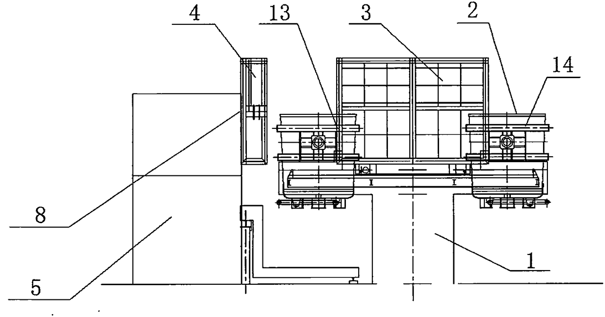
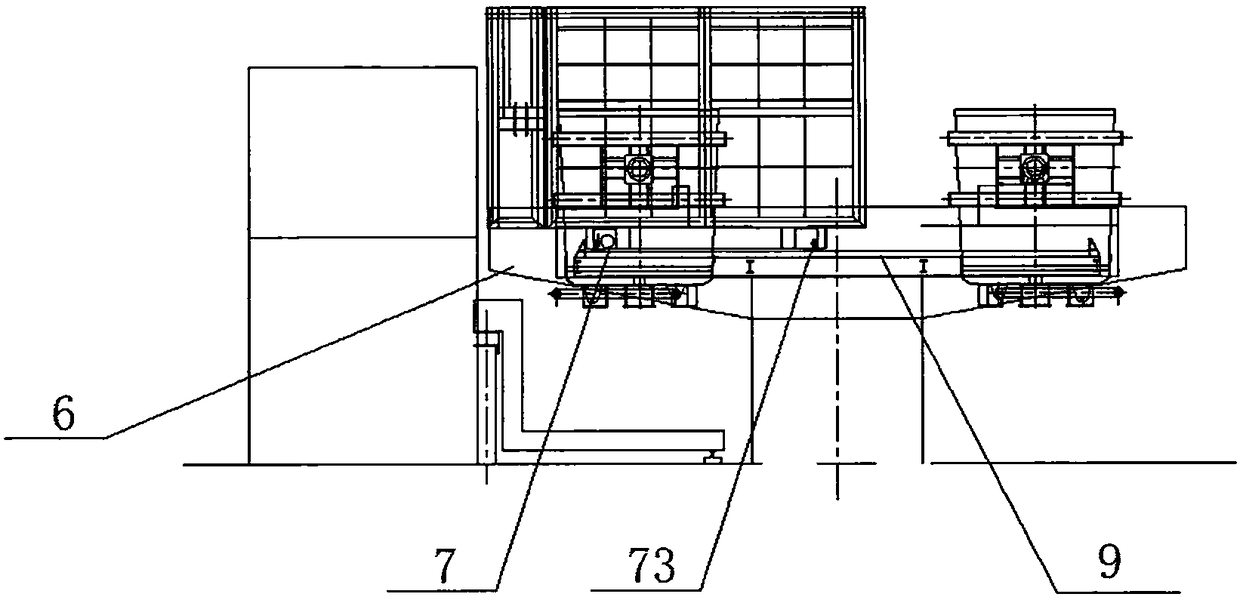
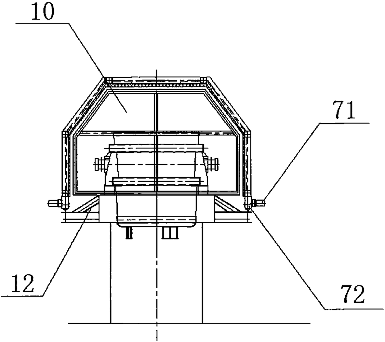
[0040] see Figure 1 ~ Figure 3 , the present invention relates to a flue gas collection device for a continuous casting ladle rotary table, comprising a machine base 1, a rotary table 6 is arranged on the machine base 1, and two left and right stations are arranged on the rotary table 6, respectively It is the pouring station 13 and the hoisting station 14, each station is equipped with a ladle 2, and a fixed partition 10 is arranged longitudinally betw...


PUM


Abstract

The invention relates to a pouring flue gas dust removal process for continuous casting big ladles. The process comprises the following steps: putting a full pack of steel ladles into a revolving table; rotating the revolving table to a pouring position; moving a movable cover on the upper parts of pouring steel ladles; performing sealing and closure between a fixed cover and the movable cover; beginning to pour the full pack of steel ladles; sucking away flue gas produced in a pouring process by a fan arranged above an operation platform through an air suction hole formed in the fixed cover,and simultaneously, preparing the full pack of steel ladles on a hoisting position; rotating the revolving table to 180 degrees when the pouring is carried out; enabling empty steel ladles to enter into the hoisting position and the full pack of steel lades to enter into the pouring position, and moving the movable cover to the upper part of the pouring position to make room for hoisting; and then repeatedly carrying out the steps. According to the pouring flue gas dust removal process for the continuous casting big ladle disclosed by the invention, through a flue gas collection device with the revolving table for the continuous casting big ladles, dispersion of flue gas is hindered in a process of pouring the big ladles, a flue gas collection ratio is increased, and a workshop environment is improved; and compared with a conventional roofing cover, the pouring flue gas dust removal process disclosed by the invention has the advantages that one-time investment and operation expenses are greatly reduced.

Description

technical field [0001] The invention belongs to the technical field of metallurgy, and in particular relates to a continuous casting ladle pouring flue gas dedusting process. Background technique [0002] The ladle turret, also known as the ladle turret, is the most commonly used equipment for carrying and supporting the ladle for pouring in modern continuous casting. It is usually installed between the molten steel receiving span and the pouring span column. Due to the particularity of the operation and equipment of the bale turret, the current mainstream form of the capture hood is the roof cover. Although the roof cover has no effect on the production operation, the temperature of the flue gas is low when the bale is poured, and the thermal lift is small. The pouring flue gas is mainly the flue gas from the nozzle to the tundish, and the flue gas is easily dispersed by the ladle. At present, in order to improve the operating environment of workers on the platform, such a...

Claims


Application Information

Patent Timeline
IPC IPC(8): B22D11/10B22D45/00
CPCB22D11/10B22D45/005
Inventor 李纪章郭龙堂
Owner 江苏朗润环保科技有限公司
Learn More