Annular four-cylinder efficient rapid prototyping device and method

A molding device and rapid technology, applied in the direction of improving energy efficiency, process efficiency, additive manufacturing, etc., can solve the problems of large amount of powder, low processing efficiency, large manual labor, etc., so as to avoid empty strokes and improve processing. Efficiency, effect of reducing manufacturing time

Inactive Publication Date: 2018-09-07
XIAN UNIV OF SCI & TECH
0 Cites 10 Cited by

AI-Extracted Technical Summary

Problems solved by technology

This method not only has low processing efficiency and a large amount of powder, but als...

Abstract

The invention discloses an annular four-cylinder efficient rapid prototyping device and method. The device comprises two laser sources, two prototyping cylinders, two transition cylinders, a powder laying roller, a rotating base, a cross partition board, two prototyping cylinder lifting supporting plates and two transition cylinder lifting supporting plates; the two prototyping cylinders and the two transition cylinders jointly form an annular four-cylinder body, the four cylinders are the same in size, the four cylinders are isolated to be independent through the cross partition board, the prototyping cylinders are used for loading prototyping parts and the powder supporting material, the prototyping cylinder lifting supporting plates are arranged inside, a prototyping part does the lifting motion, the laser sources are arranged over the two prototyping cylinders, the powder in the prototyping cylinders is scanned, irradiated and sintered, the two transition cylinders are used for recycling and supplying powder materials at the same time, the rotating base is located on the crossing position of the cross partition board, the powder laying roller mounted on the rotating base is driven to rotate, and the powder material is supplemented and recycled. The machining efficiency can be improved, the manual labor amount is reduced, and automatic manufacturing is achieved.

Application Domain

Additive manufacturing apparatusIncreasing energy efficiency

Technology Topic

Light sourceRapid prototyping +4

Image

  • Annular four-cylinder efficient rapid prototyping device and method

Examples

  • Experimental program(1)

Example Embodiment

[0015] The present invention will be described in detail below with reference to the drawings and specific embodiments, but the actual application form of the present invention is not limited to the illustrated embodiment. Based on the embodiments of the present invention, all other embodiments obtained by those of ordinary skill in the art without creative work should be deemed to fall within the protection scope of the present invention.
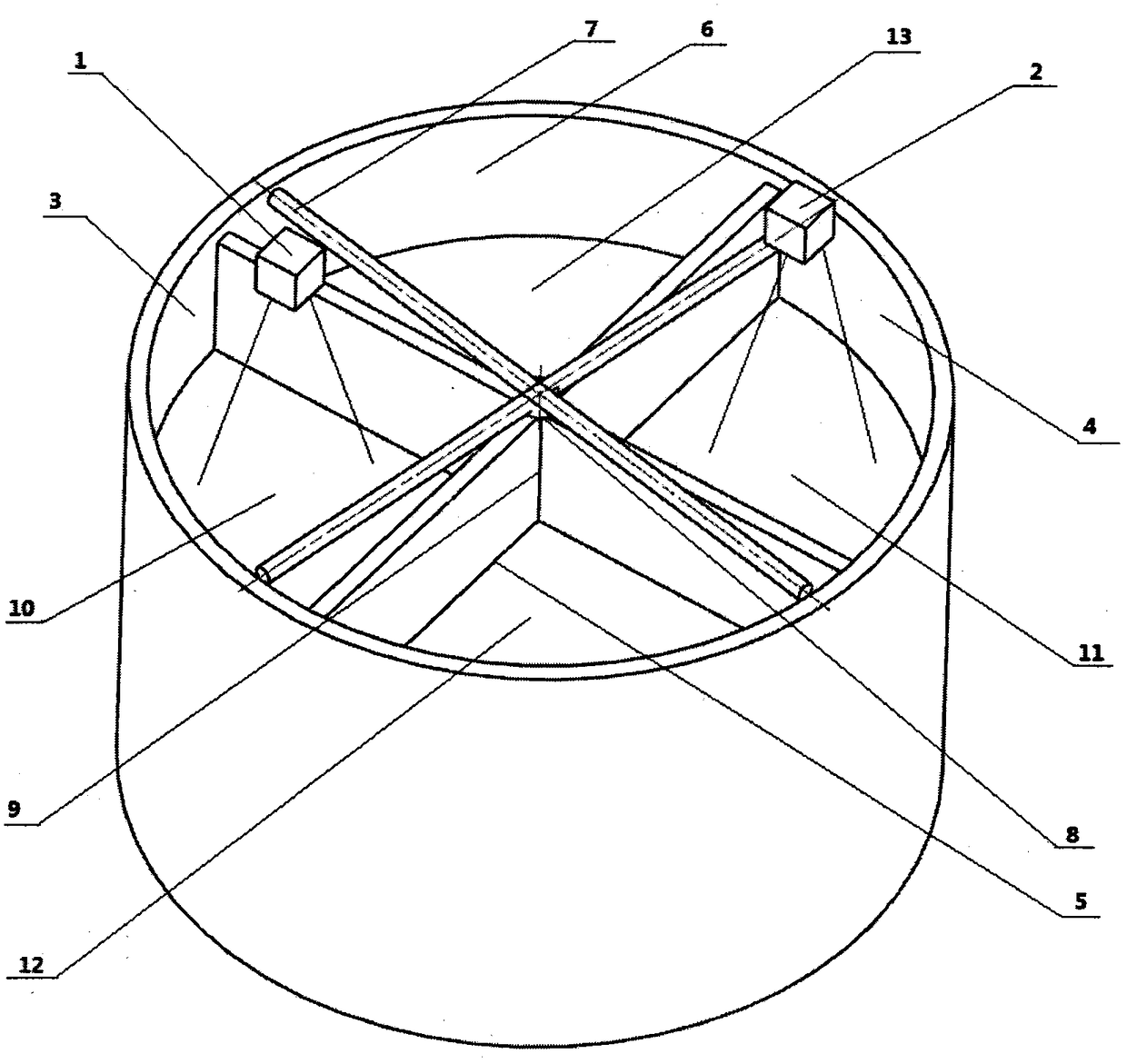
[0016] See attached figure 1 , The floating bottom laser sintering rapid prototyping device of the present invention consists of a first laser light source 1, a second laser light source 2, a first forming cylinder 3, a second forming cylinder 4, a first transition cylinder 5, and a second transition cylinder 6. , Powder spreading roller 7, rotating base 8, cross partition 9, first forming cylinder lifting pallet 10, second forming cylinder lifting pallet 11, first transition cylinder lifting pallet 12, second transition cylinder lifting pallet 13 composition. Two forming cylinders (3, 4) and two transition cylinders (5, 6) form an annular four-cylinder body, and each cylinder is the same size. The four cylinders (3, 4, 5, 6) are separated by a cross. The plates (9) are isolated from each other, the two forming cylinders (3, 4) are distributed diagonally symmetrically, the two transition cylinders (5, 6) are diagonally symmetrically distributed, and the two forming cylinders (3, 4) are used for loading The printed molded parts and powder support materials are equipped with molding cylinder lifting pallets (10, 11) for lifting and lowering the molded parts. The laser light sources (1, 2) are respectively arranged in the first molding cylinder 3 and the first molding cylinder 3 and the second molding cylinder. The second molding cylinder 4 is directly above, scanning and irradiating the powder in the molding cylinder (3, 4) for sintering molding. The two transition cylinders (5, 6) are used for recycling and supplying powder materials at the same time. The transition cylinder lifting pallet ( 12, 13), used for lifting and lowering the powder material for the purpose of recycling and supplying the powder material. The rotating base 8 is located at the intersection of the cross partition 9 and drives the powder spreading roller 7 installed on it to rotate. Used to replenish and recycle powder materials.
[0017] Such as figure 1 As shown, the working method of the annular four-cylinder high-efficiency rapid prototyping device includes the following steps:
[0018] Step 1: Turn on the rapid prototyping device and computer control system, lower the lifting pallets (12, 13) in the two transition cylinders (5, 6) to the lowest point, and fill up the powder material into the transition cylinders (5, 6) , The lifting support plates (10, 11) in the two forming cylinders (3, 4) rise to the upper surface of the cross partition 9, and the powder spreading roller 7 and the cross partition 9 are in an overlapping position;
[0019] Step 2: The computer control system converts the three-dimensional model into several two-dimensional cross-sectional contours, and transmits the thickness and contour information of each layer to the laser light source (1, 2);
[0020] Step 3: The rotating base 8 drives the powder spreading roller 7 to rotate, the lifting pallets (10, 11) in the two forming cylinders (3, 4) are lowered down by a distance of layer thickness, and the two transition cylinders (5) , 6) The lifting pallets (12, 13) in 6) rise up by a distance of one layer thickness to push out the powder material;
[0021] Step 4: The powder spreading roller 7 supplies the powder material in the two transition cylinders (5, 6) into the forming cylinders (3, 4) through a rotating movement, and the powder spreading roller 7 makes a rotating movement to the forming cylinders (3, 4). ) While spreading powder inside, the lifting pallets (12, 13) in the transition cylinders (5, 6) rise up a layer thickness distance to supply the powder material, and the lifting pallets (10, 10) in the forming cylinders (3, 4) 11) Lower a layer thickness distance, and the powder spreading roller 7 pushes the powder material supplied by the transition cylinder (5, 6) to the cross partition 9;
[0022] Step 5: After spreading a layer of powder material in the forming cylinder (3, 4), at this time, the powder spreading roller 7 overlaps the cross partition 9 and the laser light source (1, 2) is opposite to the forming cylinder (3, 4) The first layer of laser scanning is performed on the powder material inside, so that the powder material is sintered according to the contour information of the sequential layer;
[0023] Step 6: Repeat steps 4 and 5 until the manufacture of molded parts is completed;
[0024] Step 7: Take out the molded part, the lifting pallets (10, 11) of the forming cylinder rise, the lifting pallets (12, 13) of the transition cylinder drop, and the powder spreading roller 7 recovers the excess powder material of the forming cylinder (3, 4) to the transition cylinder In (5, 6), the original position is finally restored and the printing is completed.

PUM

no PUM

Description & Claims & Application Information

We can also present the details of the Description, Claims and Application information to help users get a comprehensive understanding of the technical details of the patent, such as background art, summary of invention, brief description of drawings, description of embodiments, and other original content. On the other hand, users can also determine the specific scope of protection of the technology through the list of claims; as well as understand the changes in the life cycle of the technology with the presentation of the patent timeline. Login to view more.

Similar technology patents

Intelligent assembly line for cleaning garbage cans

ActiveCN106494849AImprove processing efficiencySimple and reasonable configuration
Owner:YANGZHOU JINWEI ENVIRONMENTAL PROTECTION TECH CO LTD

Classification and recommendation of technical efficacy words

  • Improve processing efficiency
  • avoid empty trips

Full-automatic cloth paving and cutting integrated machine

InactiveCN106592194AImprove processing intelligenceImprove processing efficiency
Owner:CHONGQING UNIV OF TECH

Bidirectional quantitative powder supplying and spreading device for additive manufacturing

PendingCN109795110Aavoid empty tripsImprove spreading efficiency
Owner:SUZHOU XIDIMO THREE DIMENSIONAL PRINTING TECH CO LTD
Why Eureka
Try Eureka