Security robot

A robot and security technology, applied in the direction of manipulators, closed-circuit television systems, manufacturing tools, etc., can solve the problems of not meeting the working requirements of security robots, poor corrosion resistance, operation stability and control influence, etc.

Active Publication Date: 2018-09-07
中山火炬高新企业孵化器有限公司
View PDF5 Cites 26 Cited by
  • Summary
  • Abstract
  • Description
  • Claims
  • Application Information

AI Technical Summary

Problems solved by technology

[0004] 1. The same security precautions are widely used in all walks of life. The traditional security system mainly uses fixed-position monitoring equipment to collect images and other signals to cooperate with personnel inspections. It requires a large amount of monitoring equipment and human resources, resulting in large monitoring dead ends. Failure to issue an alarm message in time after a problem is found
[0005] 2. The existing front wheel shock absorption structure of security robots usually adopts ball bearing cups. The rolling groove made of ordinary steel has low hardness and rough surface, and due to poor sealing and poor corrosion resistance, the shock absorber and the frame, The handlebar connection is often not tight, and often has a frame, which has some impact on running stability and control. At the same time, the shock absorption performance is poor, which is easy to cause the security robot to roll over in bumpy areas, affecting the inspection efficiency.
[0006] 3. The button collection and locking structure of the existing security robot is relatively complicated, which is inconvenient to use. The

Method used


Image

  • Security robot
  • Security robot
  • Security robot

Examples


Embodiment Construction

[0038] In order to make the purpose, technical solutions and beneficial effects of the present invention more clear, the preferred embodiments of the present invention will be described in detail below in conjunction with the accompanying drawings, so as to facilitate the understanding of technical personnel.

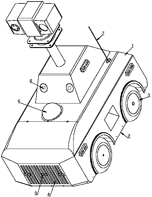
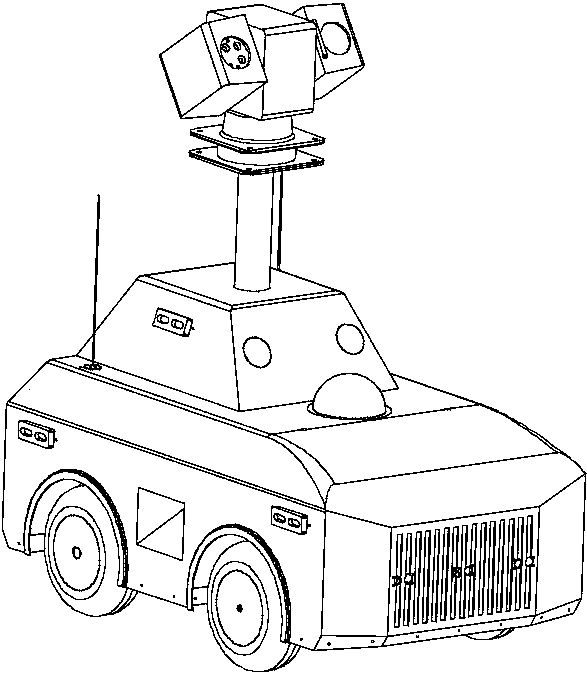
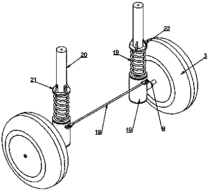
[0039] Such as Figure 1-2 As shown, the security robot includes a housing 1, a bottom plate 2, a wheel 3, a front wheel shock-absorbing and wrist group structure, a key set and locking structure, a multi-degree-of-freedom scalable structure, a heat dissipation system, a controller 67, and a shell The body 1 and the base plate 2 are connected by bolts, and wheels 3 are installed on both sides of the shell 1. The front wheel shock-absorbing and wrist group structure is set on the wheels 3, and the button assembly and locking structure is set on the support of the top of the shell 1. A multi-degree-of-freedom telescopic structure is installed on the side wall of the platf...


PUM


Abstract

The invention relates to a security robot, and belongs to the technical field of security robots. The security robot comprises a shell, a base plate, wheels, a front-wheel damping wrist set structure,a key grouping and locking structure, a multi-degree-of-freedom telescopic structure, a heat-dissipation system and a controller. According to the security robot, automatic monitoring can be achieved, and monitoring information can be transmitted in real time; all switches of a key box are effectively grouped, so that management is facilitated, and disorder of keys is effectively avoided; by adoption of the structural design of the front dual-damping wrist set structure, effective damping can be achieved, and steering is easy; through a multi-degree-of-freedom lifting adjustment structure, multi-degree-of-freedom adjustment of a camera of the security robot can be achieved, different work requirements are met, and patrolling information is effectively synchronized; and through the structural design of the circulating heat-dissipation system, the stability of the temperature and humidity of the internal environment of the security robot can be ensured, and the heat-dissipation efficiency is improved.

Description

technical field [0001] The invention belongs to the technical field of security robots, and in particular relates to a security robot. Background technique [0002] At present, our country has entered a critical period of reform and development, social transformation and transition, profound changes in the economic system, rapid changes in the social structure, accelerated adjustment of the interest pattern, rapid changes in ideas and concepts, and a large increase in floating population. This unprecedented social change, While bringing great vitality to the development and progress of our country, various security risks have also emerged, especially reflected in the security field of the park. The high level of social security has brought huge pressure to the community security system. [0003] But the existing security system mainly has the following defects: [0004] 1. The same security precautions are widely used in all walks of life. The traditional security system ma...

Claims


Application Information

Patent Timeline
IPC IPC(8): B25J11/00B25J5/00B25J19/00B25J19/02H04N7/18
CPCB25J5/007B25J11/00B25J19/0054B25J19/0091B25J19/023H04N7/18
Inventor 龙亿吴润锋刘志杰
Owner 中山火炬高新企业孵化器有限公司
Why Eureka
Try Eureka