
Plastic impeller mold shape follow-up waterway cooling system

A cooling system and waterway technology, which is applied to household appliances, other household appliances, household components, etc., can solve the problems of high cooling time cost, high production cost, and staggering production cost, so as to shorten the development cycle, increase production capacity, and optimize the shape Effect with shunt diameter

Pending Publication Date: 2018-09-07
上海迪质特信息科技有限公司
View PDF0 Cites 4 Cited by
  • Summary
  • Abstract
  • Description
  • Claims
  • Application Information

AI Technical Summary

Problems solved by technology

At present, the products produced by the impeller mold using the traditional waterway scheme, the outline (end runout, radial runout) is basically controlled at about 0.8mm, and some products have to be corrected after the tolerance is exceeded, and the production cost is further increased; In terms of the control of the rotation unbalance value of plastic impeller products, the value of the rotation unbalance value of traditional impeller products is generally around 12mg.mm, while the ideal value required by the drawings is below 4mg.mm. When the rotation unbalance value exceeds the standard during product production Generally, after measuring with a dynamic balancing machine, the balance is corrected by adding counterweights. Some products often need to be inspected and compensated for 2-3 times. The production cost of this kind of measurement and calibration is relatively astonishing.
[0004] On the other hand, in order to improve the quality of products deformed due to uneven cooling, traditional waterway molds deliberately prolong the cooling time of plastic parts. This not only has a very limited improvement effect, but also significantly reduces product production efficiency.
In the traditional waterway impeller mold, the product production cycle is about 60 seconds. Sometimes in order to improve product deformation, the injection molding cycle even exceeds 75 seconds. According to estimates, about 48-60 seconds of the entire cycle are spent on cooling. , the cooling cycle of plastic parts occupies about 80% of the entire molding cycle, obviously, the cost of cooling time is relatively high

Method used


Image

  • Plastic impeller mold shape follow-up waterway cooling system
  • Plastic impeller mold shape follow-up waterway cooling system
  • Plastic impeller mold shape follow-up waterway cooling system

Examples


Embodiment

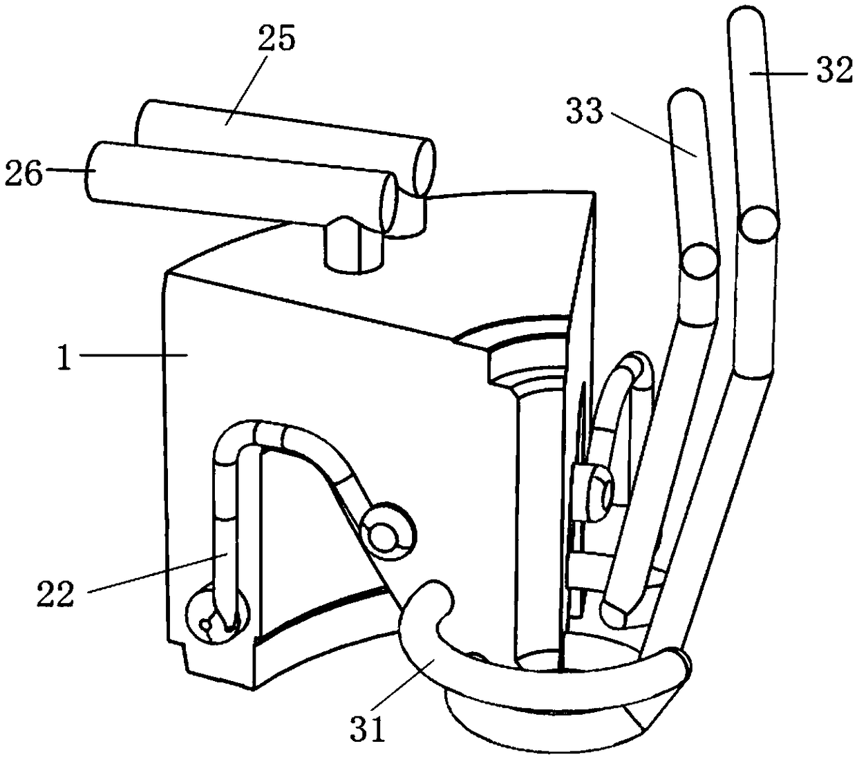
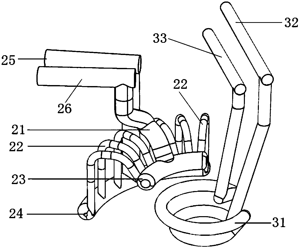
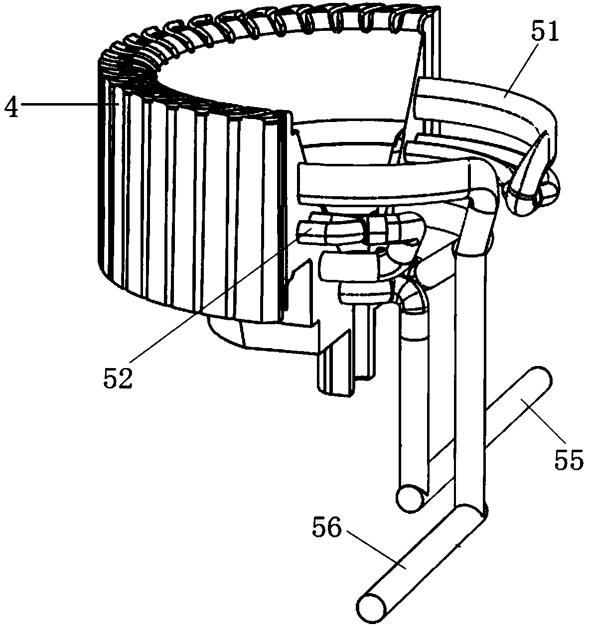
[0022] specific embodiment Figure 1 to Figure 4 As shown, the present invention includes a cavity 1, a core 4, a cavity follow-the-shape connecting waterway 21, a mold cavity follow-the-shape shunting waterway 22, an arc-shaped waterway 23 inside the cavity, an arc-shaped waterway 24 outside the cavity, and an inlet outside the cavity. Water pipeline 25, water outlet pipeline 26 outside the cavity, spiral annular waterway 31, water inlet pipeline inside the cavity 32, water outlet pipeline inside the cavity 33, annular waterway 51 on the upper side of the core, parallel waterway 52, core bridge Waterway 53, ring-shaped waterway 54 on the lower side of the core, core water inlet pipeline 55 and core outlet pipeline 56, cavity 1 and core 4 are both circular structures, the cavity is connected with the shape of the waterway 21, and the cavity is shaped with the shape The shunt waterway 22, the curved waterway 23 inside the cavity, the curved waterway 24 outside the cavity, and t...


PUM


Abstract

The invention discloses a shape follow-up waterway cooling system in the technical field of plastic impeller mold cooling. The shape follow-up waterway cooling system comprises a mold cavity and a mold core. A shape follow-up connection waterway, a shape follow-up distribution waterway, an inner side arc-shaped waterway, an outer side arc-shaped waterway and a spiral annular waterway are all arranged in the mold cavity. The mold cavity outer side arc-shaped waterway is arranged on the outer side of the mold cavity. The mold cavity inner side arc-shaped waterway and the spiral annular waterwayare arranged on the inner side of the mold cavity. An outer side water outlet pipeline is connected with the inner side arc-shaped waterway through the shape follow-up connection waterway. A mold coreupper side annular waterway, a mold core parallel-connection waterway and a mold core lower side annular waterway are arranged in the mold core sequentially from top to bottom. In the shape follow-upwaterway cooling system, the waterways can be distributed in a mold kernel evenly, in this way, the best product forming temperature can be ensured, the product injection molding period of about 60-70 seconds in a traditional cooling scheme can be shortened to about 40-50 seconds through even regulation of mold temperature, and the defect rate caused by uneven product cooling can also be lowered.

Description

technical field [0001] The invention relates to a cooling system in the technical field of plastic impeller molds, in particular to a cooling system with conformal waterway design. Background technique [0002] Plastic impellers have been widely used in 3C electronic products, white goods, automobiles and other fields. At the same time, due to technological innovation and continuous improvement of product quality, the continuous pursuit of high-quality impellers in the above fields also determines the dimensional accuracy and dynamic balance of plastic impellers. And other functional index parameters have been improved, which also ushers in new challenges for the manufacturing and molding process of plastic impellers. As we all know, in the injection molding of plastic parts, the temperature of the mold is adjusted through temperature control equipment such as an external mold temperature controller, and the corresponding medium is controlled to flow into the water channel o...

Claims


Application Information

Patent Timeline
IPC IPC(8): B29C45/73B29L31/08
CPCB29C45/7312B29L2031/08
Inventor 樊洋龙何友权
Owner 上海迪质特信息科技有限公司
Learn More