Laser radar rotation control method for target detection

A laser radar and target detection technology, applied in the direction of radio wave measurement systems, instruments, etc., can solve the problems of not considering the operating speed of the carrier platform, reducing the effective detection distance of the system, and the effect of the effect

Active Publication Date: 2018-09-07
NAT UNIV OF DEFENSE TECH
View PDF8 Cites 12 Cited by
  • Summary
  • Abstract
  • Description
  • Claims
  • Application Information

AI Technical Summary

Problems solved by technology

[0003] For the target detection of laser radar, it is usually devoted to the research on how to use the point cloud information obtained by laser radar to realize the accurate detection of obstacles. There is no research on the quality of the obtained point cloud information. However, in the case of unmanned vehicles In the actual application of the laser radar, there is a working blind spot and the farther the target is from the laser radar, the sparser the surface point cloud obtained is. The sparse point cloud will further reduce the effective detection distance of the system, and the low-quality point cloud data is also the cause The system effectively detects the root cause of the limited distance
[0004] In order to make up for the disadvantage of the weak geometric shape information of the target acquired by single-line lidar and improve the quality of point cloud data acquired by lidar, one method is to use 2D lidar or 3D laser scanning to achieve uniform scanning, where 3D laser scanning is usually a combination of 2D laser The radar and IMU (inertial measurement unit) are fixed at one end of the spri

Method used


Image

  • Laser radar rotation control method for target detection
  • Laser radar rotation control method for target detection
  • Laser radar rotation control method for target detection

Examples


Embodiment Construction

[0060] The present invention will be further described below in conjunction with the accompanying drawings and specific preferred embodiments, but the protection scope of the present invention is not limited thereby.

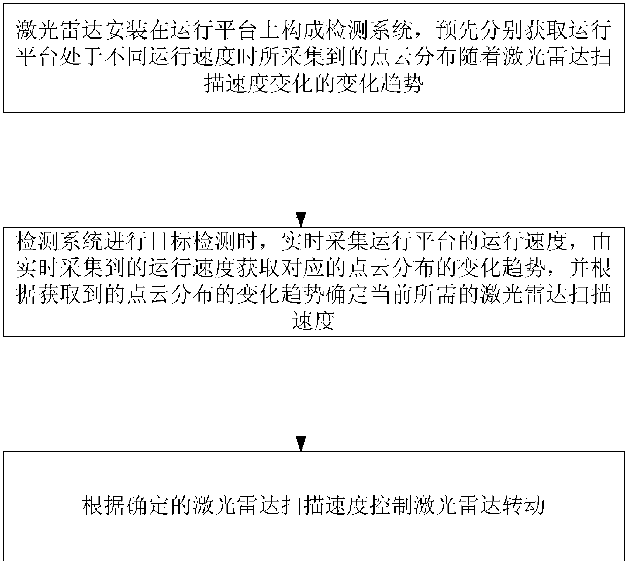
[0061] Such as figure 1 As shown, the laser radar rotation control method used for target detection in this embodiment, the steps include:

[0062] S1. Install the lidar on the operating platform to form a detection system, and obtain the point cloud distribution collected when the operating platform is at different operating speeds according to the installation location information of the lidar and the location information of the detection target in advance. The changing trend of the speed change;

[0063] S2. When the detection system performs target detection, the running speed of the operating platform is collected in real time, and the corresponding change trend of the point cloud distribution is obtained from the real-time collected running speed, and the...


PUM


Abstract

The invention discloses a laser radar rotation control method for target detection. The laser radar rotation control method comprises the steps that S1, a laser radar is installed on an operating platform to form a detection system, the change trends acquired at different operating speeds of the operating platform that point cloud distributions change with the scanning speed of the laser radar areobtained; S2, when the detection system performs target detection, the operating speed of the operating platform is acquired in real time, the change trend of corresponding point distribution is obtained according to the operating speed acquired in real time, and the current required laser radar scanning speed is determined according to the change trend of the point distribution; S3, the laser radar is controlled to rotate according to the scanning speed of the laser radar determined in the step S2 so as to complete target detection. The laser radar rotation control method has the advantagesof being simple to achieve, small in working blind zone and large in effective detection distance and making scanned point cloud data rich.

Description

technical field [0001] The invention relates to the technical field of target detection in unmanned systems, in particular to a laser radar rotation control method for target detection. Background technique [0002] As a new type of active ranging sensor, lidar has high measurement accuracy, long detection distance, and is not affected by changes in ambient light. It can quickly obtain target information complementary to images, and is especially suitable for obstacle detection in unmanned systems. . Pedestrian and vehicle detection has always been a hot topic in the research fields of intelligent transportation, unmanned vehicles, and automobile safety assisted driving. Pedestrian detection based on visual information is easily affected by illumination, target attitude changes, and occlusion, which reduces its detection accuracy; In the realistic and complex traffic environment, the higher the accuracy of target detection and the farther the effective detection distance, t...

Claims


Application Information

Patent Timeline
IPC IPC(8): G01S7/481G01S7/486
CPCG01S7/4817G01S7/4868
Inventor 尹栋李杰相晓嘉李梦洁
Owner NAT UNIV OF DEFENSE TECH
Why Eureka
Try Eureka