
Communication base station and beamforming method thereof

A beamforming method and technology of a communication base station, which are applied in the field of beamforming technology, can solve the problems of large deviation between the azimuth angle measurement value and the actual value, unfavorable beamforming algorithm application, inaccurate azimuth angle measurement and other problems, so as to avoid Interference, increased cell throughput, effect of reduced frequency

Inactive Publication Date: 2018-09-07
QIANXUN SPATIAL INTELLIGENCE INC
View PDF7 Cites 8 Cited by
  • Summary
  • Abstract
  • Description
  • Claims
  • Application Information

AI Technical Summary

Problems solved by technology

[0003] In the prior art, the beamforming method based on satellite positioning technology, due to the low positioning accuracy of the mobile terminal, there is an error of 5-10 meters in the horizontal direction, and an error of 10-20 meters in the elevation, resulting in the difference between the base station antenna and the mobile terminal in three-dimensional space. The azimuth angle calculation is inaccurate, and the azimuth angle measurement value deviates greatly from the actual value, which is not conducive to the application of the beamforming algorithm and is not suitable for the formation of narrow beams
[0004] In addition, the existing differential positioning technology generally performs high-precision positioning calculations on the mobile terminal side, which has the problem of high power consumption. The mobile terminal also needs to obtain real-time differential data, which has the problem of high traffic.

Method used

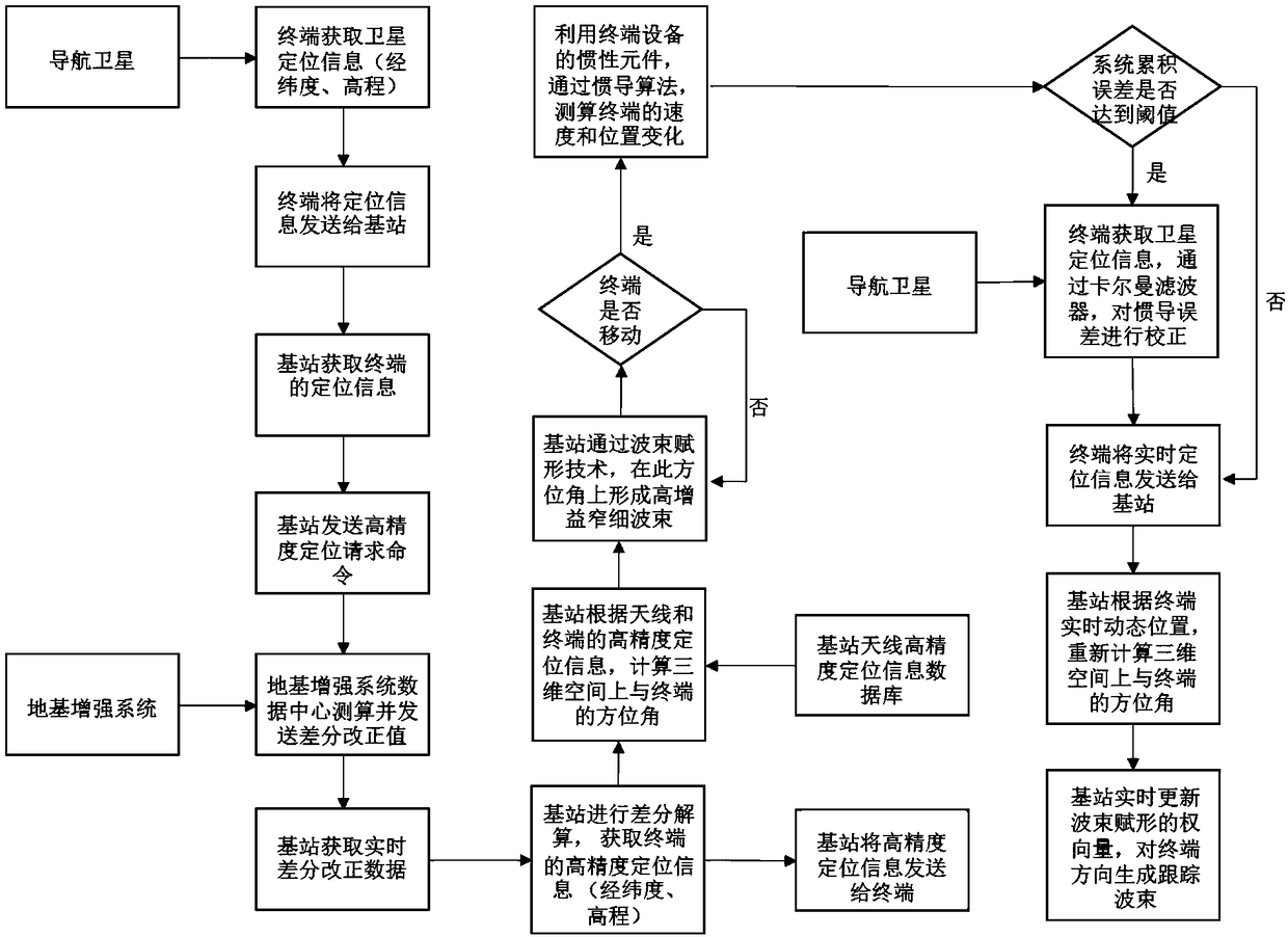

Image

  • Communication base station and beamforming method thereof
  • Communication base station and beamforming method thereof
  • Communication base station and beamforming method thereof

Examples


Embodiment Construction

[0026] In the following description, many technical details are proposed in order to enable readers to better understand the application. However, those skilled in the art can understand that without these technical details and various changes and modifications based on the following implementation modes, the technical solution claimed in each claim of the present application can be realized.

[0027] In order to make the purpose, technical solution and advantages of the present invention clearer, the following will further describe the implementation of the present invention in detail in conjunction with the accompanying drawings.

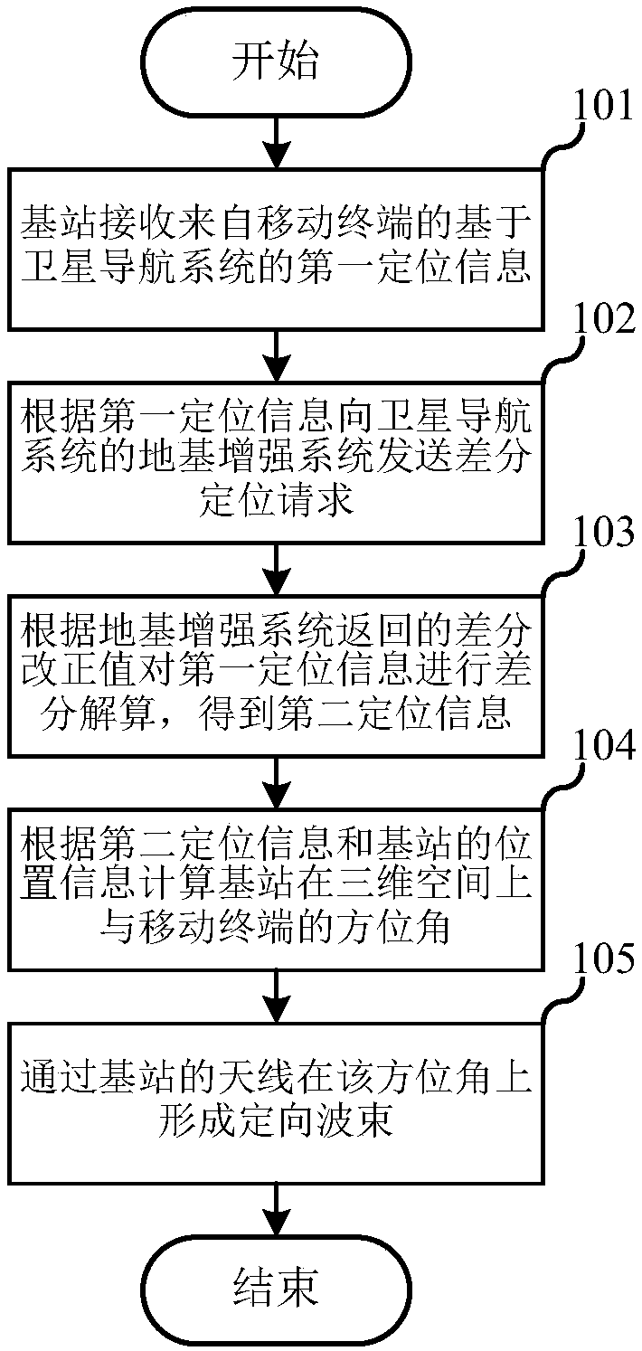
[0028] The first embodiment of the present invention relates to a beamforming method of a communication base station. figure 1 is a schematic flowchart of the beamforming method of the communication base station.

[0029] Specifically, as figure 1 As shown, the beamforming method of the communication base station includes the following steps:

...

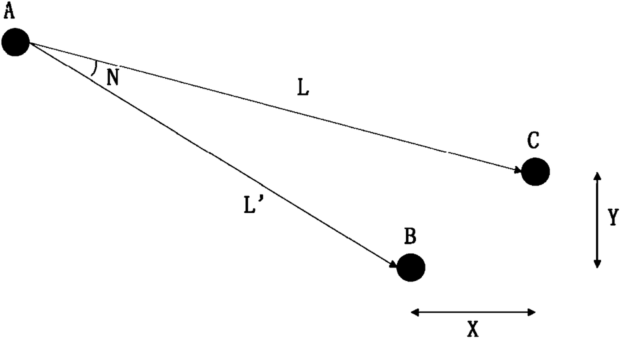

PUM


Abstract

The invention relates to the field of mobile communication, and discloses a communication base station and a beamforming method thereof. The beamforming method of the communication base station comprises the following steps that the base station receives first positioning information based on a satellite navigation system from a mobile terminal; the base station sends a differential positioning request to a ground-based augmentation system of the satellite navigation system according to the first positioning information; the base station performs differential calculation on the first positioning information according to a differential correction value returned from the ground-based augmentation system, so as to obtain second positioning information; and the base station calculates a position angle between the base station and the mobile terminal in three-dimensional space according to second positioning information and known position information of a base station antenna, and forms a directional beam for the mobile terminal in the position angle through the base station antenna. The beamforming method of the communication base station can improve link quality of wireless communication and increase cell throughput.

Description

technical field [0001] The invention relates to the field of mobile communication and satellite navigation, in particular to beam forming technology in mobile communication. Background technique [0002] Beamforming (BF) is a signal preprocessing technology based on an antenna array. Beamforming generates directional beams by adjusting the weighting coefficients of each array element in the antenna array, so that significant array gain can be obtained. Therefore, beamforming technology has great advantages in expanding coverage, improving edge throughput, and interference suppression. Due to the spatial selectivity brought by beamforming, there is a close relationship between beamforming and SDMA. Beamforming techniques applied in real systems may have different goals, such as focusing on link quality improvement (coverage extension, user throughput improvement) or addressing multi-user issues (such as cell throughput and interference cancellation / avoidance). [0003] In ...

Claims


Application Information

Patent Timeline
IPC IPC(8): H04W4/02H04W16/28H04W64/00H04B7/0408H04B7/06H04B7/185
CPCH04B7/0408H04B7/0617H04B7/18554H04W4/023H04W16/28H04W64/006
Inventor 陈渊暐
Owner QIANXUN SPATIAL INTELLIGENCE INC
Learn More