Gravity-based unordered swinging-type rare earth feed liquid mixing equipment
A rare earth material liquid and mixing equipment technology, applied in the direction of shaking/oscillating/vibrating mixer, mixer, dissolution, etc., can solve the problems affecting the use of rare earth material liquid, difficult to stir and use, and the rare earth material liquid cannot be completely mixed, etc.
- Summary
- Abstract
- Description
- Claims
- Application Information
AI Technical Summary
Problems solved by technology
Method used
Image
Examples
Embodiment 1
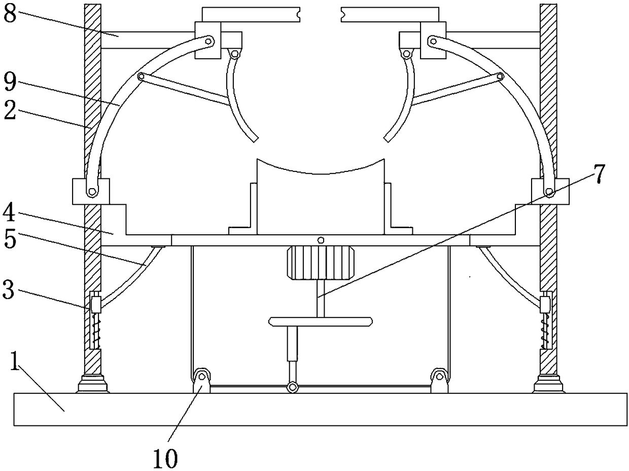
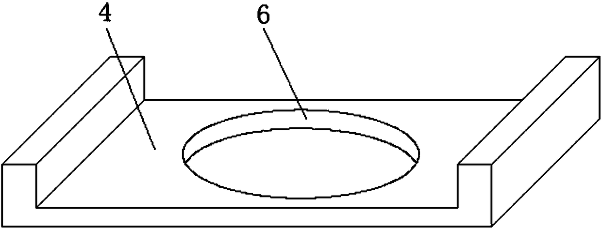
[0045] Such as Figure 1-2 As shown, the present invention provides a technical solution: a kind of random swing type rare earth material liquid mixing equipment based on gravity, including a working base 1, and side plates 2 are fixedly connected to the left and right sides of the top of the working base 1, and the two Limiting grooves 3 are provided on the sides of the two side plates 2 that are close to each other, and a U-shaped placing plate 4 positioned above the limiting groove 3 is movably connected between the two side plates 2, and the left and right sides of the bottom of the U-shaped placing plate 4 are arranged A resettable support mechanism 5 is fixedly connected, and a transparent circular groove 6 is opened on the bottom of the U-shaped placement plate 4, and a swinging rotation mechanism 7 is arranged between the front and back of the inner wall of the circular groove 6, and the two side plates 2 The uppermost moving horizontal plate 8 is fixedly connected to ...
Embodiment 2
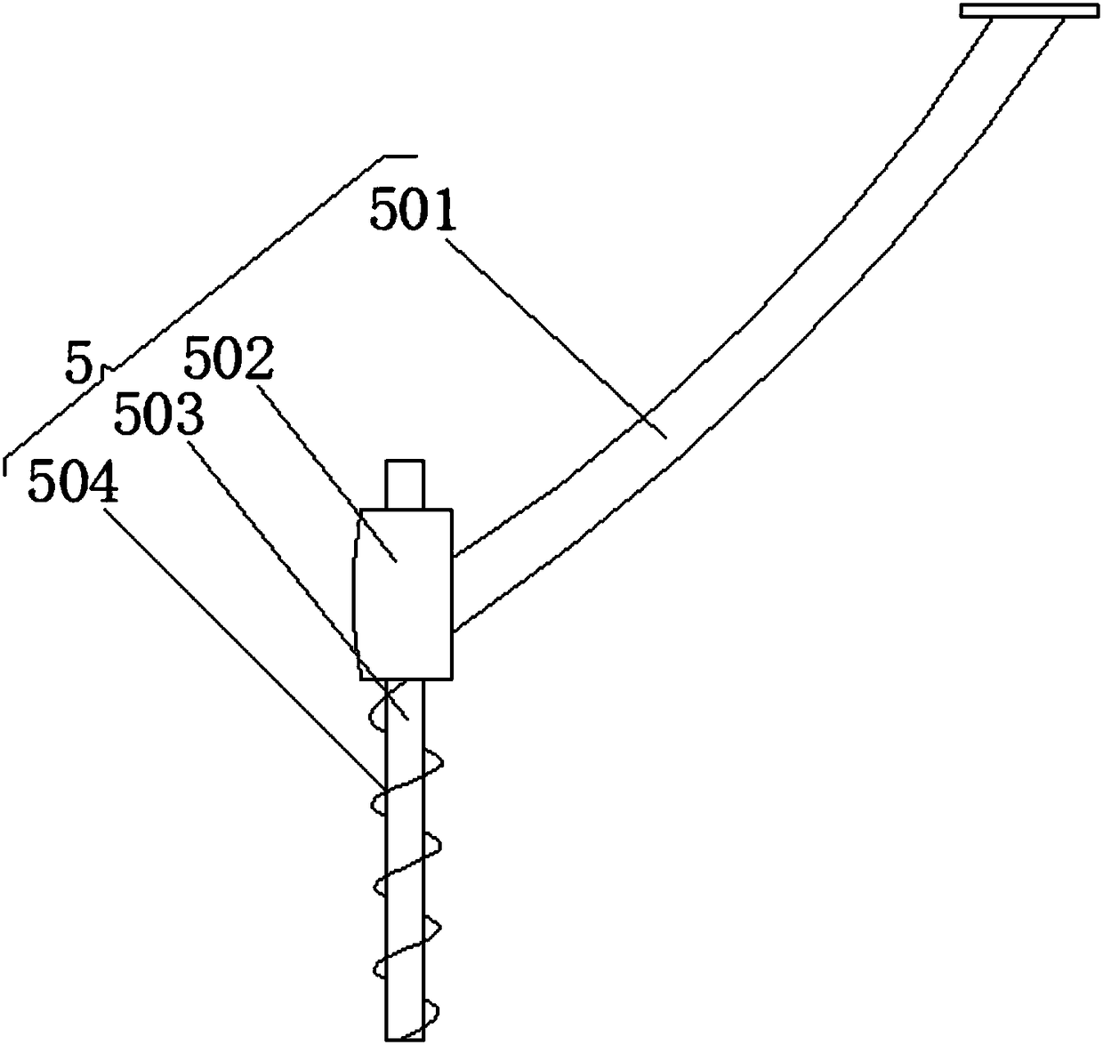
[0047] Such as Figure 1-3 As shown, on the basis of Embodiment 1, the present invention provides a technical solution: the resettable support mechanism 5 includes an arc-shaped plate 501, the concave surface of the arc-shaped plate 501 is upward, and the tangent direction of the top of the arc-shaped plate 501 is vertical direction, the tangent direction of the side of the arc-shaped plate 501 is the horizontal direction, by setting the arc-shaped plate 501, the concave surface of the arc-shaped plate 501 is upward, so that when moving up and down, the arc-shaped plate 501 can support a certain bearing force. The setting of the shape increases the downward stress, makes the bearing capacity stronger, and can protect the U-shaped placement plate 4 from falling or damage, and the top of the arc-shaped plate 501 is fixedly connected on the U-shaped placement plate 4, and the arc-shaped plate The other end of 501 is fixedly connected with annular slider 502, and the inside of ann...
Embodiment 3
[0049] Such as Figure 1-5As shown, on the basis of Embodiment 1 and Embodiment 2, the present invention provides a technical solution: the swing-type rotating mechanism 7 includes two rotating rods 701, and the two rotating rods 701 are fixedly connected to the front of the inner wall of the circular groove 6 and the back side, a swinging disc 702 is fixedly connected between the two rotating rods 701, and the top of the disc 702 is fixedly connected to the feeding cylinder 704 through the angle steel 703. The material of the angle steel 703 is Q275 steel, the yield point is 275MPa, and the standard is GB / T700-2006, by setting the angle steel 703, the angle steel 703 can protect the feeding cylinder 704 from falling when tilted and swinging, and can work many times, and also greatly prolong the service life of the machine. The feeding cylinder 704 The top of the circular plate is circular, and the height of the outer ring at the top of the feeding barrel 704 is greater than t...
PUM
| Property | Measurement | Unit |
|---|---|---|
| Yield point | aaaaa | aaaaa |
Abstract
Description
Claims
Application Information
 - R&D
- Intellectual Property
- Life Sciences
- Materials
- Tech Scout
- Unparalleled Data Quality
- Higher Quality Content
- 60% Fewer Hallucinations
Browse by: Latest US Patents, China's latest patents, Technical Efficacy Thesaurus, Application Domain, Technology Topic, Popular Technical Reports.
© 2025 PatSnap. All rights reserved.Legal|Privacy policy|Modern Slavery Act Transparency Statement|Sitemap|About US| Contact US: help@patsnap.com


