
Chain drive differential mechanism for independent suspension between wheels

A technology of independent suspension and differential mechanism, which is applied in the field of differential devices and chain transmission differential mechanisms, can solve the problems of high cost, difficult disassembly and maintenance, and immaturity, and meet the requirements of reducing the working angle and improving structural stability , the effect of reducing the distance

Pending Publication Date: 2018-09-11
SIYANG YONGSHI MACHINERY MFG CO LTD
View PDF0 Cites 0 Cited by
  • Summary
  • Abstract
  • Description
  • Claims
  • Application Information

AI Technical Summary

Problems solved by technology

[0002] Most of the existing independent suspensions are the combination mechanism of the shaft-driven independent suspension and the differential. Since the shaft-driven independent suspension requires gear meshing, it is not easy to disassemble and maintain, and it has a large volume, cannot be installed in a small space, and is expensive. However, the chain drive independent suspension technology is still immature, lacks a mechanism connected with the differential, and cannot meet market demand, making it impossible to efficiently replace and install the independent suspension with differential for vehicles originally equipped with chain drive

Method used


Image

  • Chain drive differential mechanism for independent suspension between wheels
  • Chain drive differential mechanism for independent suspension between wheels
  • Chain drive differential mechanism for independent suspension between wheels

Examples


Embodiment Construction

[0020] In order to make it easy to understand the technical means, creative features, goals and effects achieved by the present invention, how the patent of the present invention is implemented is further explained in conjunction with the accompanying drawings:

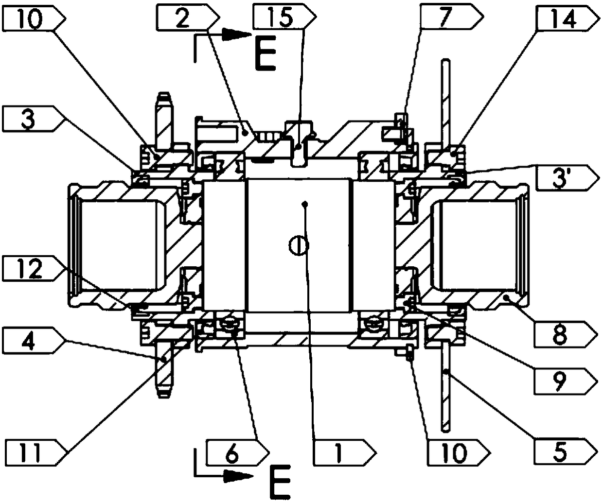
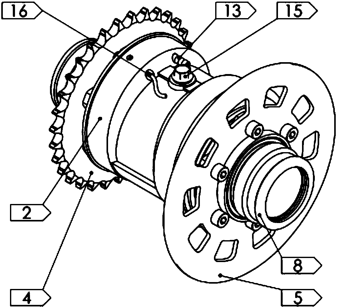
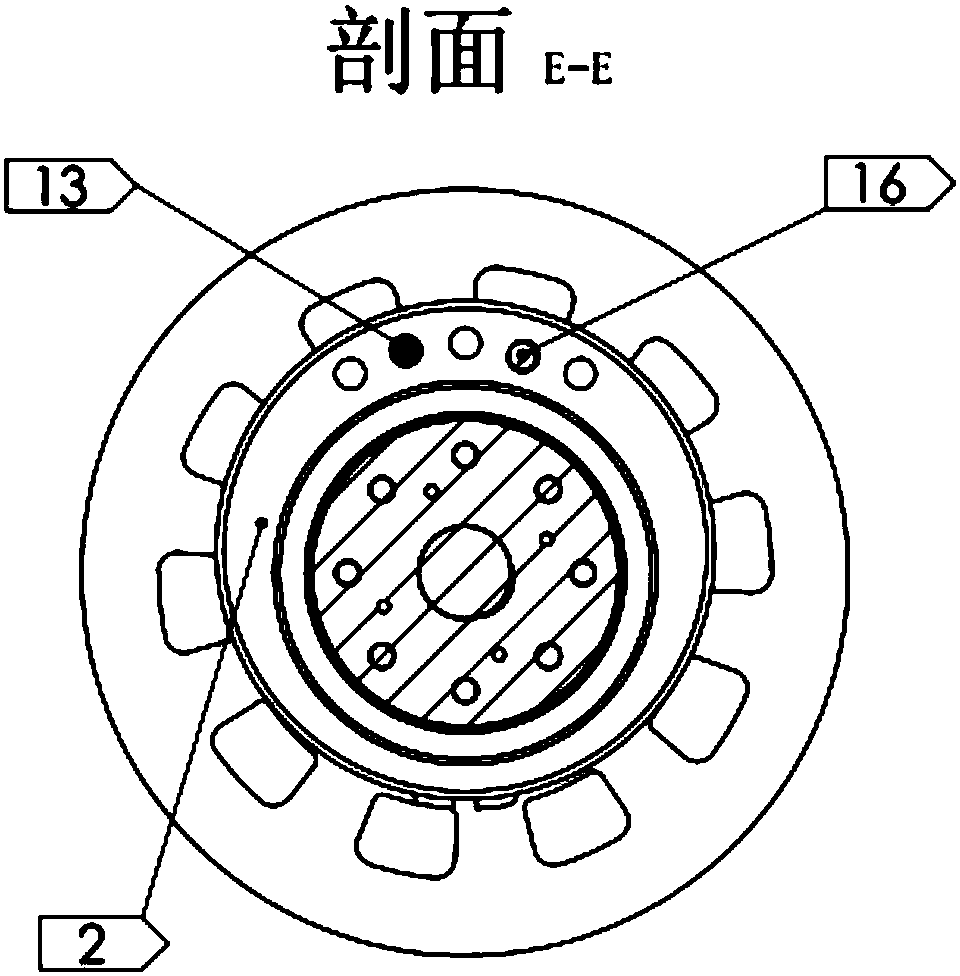
[0021] A chain transmission differential mechanism for independent suspension between wheels, such as figure 1 As shown, the differential 1 is installed in the eccentric sleeve 2 through the bearing 6, the left end cover 3 and the right end cover 3' are respectively connected with the differential 1 with bolts 9 to form a whole, and the sprocket disc 4 and the brake disc 5 are respectively used The bolt 14 device is fixed on the left end cover 3 and the right end cover 3', and the eccentric sleeve 2 can be placed in the rear flat fork 17 of the vehicle frame to rotate to adjust the chain tightness (this is to use the eccentric principle to change the large fly and small sprocket discs). Fly (little fly on the engine) ...


PUM


Abstract

The invention relates to a chain drive differential mechanism for independent suspension between wheels. The mechanism mainly comprises a differential mechanism body, an eccentric sleeve, an end cover, a chain sprocket, a brake disc, a bearing, a brake bracket and universal spindle couplings; the eccentric sleeve movably sleeves the outer circumference of the differential mechanism body through the bearing; the end cover comprises a left end cover body and a right end cover body which are fixed to openings formed in the left end and the right end of the differential mechanism body respectively; the chain sprocket and the brake disc are coaxially fixed to the left end cover body and the right end cover body respectively; the brake bracket is assembled on one side of the eccentric sleeve, and multiple through holes are formed in the side wall of the other side of the eccentric sleeve, wherein a speed sensor and an exhaust nozzle are installed in two through holes; one ends of the two universal spindle couplings penetrate through the left end cover body and the right end cover body respectively to be fixedly connected with one end of the differential mechanism body. Accordingly, the mechanism of chain transmission power and the independent suspension structure are combined together, the differential mechanism body is assembled in the eccentric sleeve mainly, the size is small, theweight is low, the independently suspended universal spindle couplings can be embedded into the end cover, the size is reduced, the distance between the left and right couplings is reduced, the independent suspension work angle requirements are greatly lowered, and whole structure stability is improved.

Description

technical field [0001] The invention relates to a differential device, specifically a chain drive differential mechanism for independent suspension between wheels, belonging to the field of mechanical transmission equipment. Background technique [0002] Most of the existing independent suspensions are the combination mechanism of the shaft-driven independent suspension and the differential. Since the shaft-driven independent suspension requires gear meshing, it is not easy to disassemble and maintain, and it has a large volume, cannot be installed in a small space, and is expensive. However, the independent suspension technology of the chain drive is still immature, lacks the mechanism connected with the differential, and cannot meet the market demand, so that the vehicle originally equipped with the chain drive cannot be efficiently replaced with an independent suspension with a differential. Contents of the invention [0003] The technical problem to be solved by the pr...

Claims


Application Information

Patent Timeline
IPC IPC(8): B62M9/00B62M9/16
CPCB62M9/00B62M9/16
Inventor 吴春来
Owner SIYANG YONGSHI MACHINERY MFG CO LTD
Features
  • Generate Ideas
  • Intellectual Property
  • Life Sciences
  • Materials
  • Tech Scout
  • Unparalleled Data Quality
  • Higher Quality Content
  • 60% Fewer Hallucinations
Learn More