Automatic labeling method for photovoltaic components

A photovoltaic module and automatic technology, which is applied in labeling machines, labels, packaging, etc., can solve the problems of component appearance, performance parameters, non-uniform label sticking position, incomplete label gas discharge, etc., to avoid labeling Does not correspond to the barcode, reduces the operation process, and reduces the effect of labeling raw material costs

Inactive Publication Date: 2018-09-11
格润智能光伏南通有限公司
View PDF7 Cites 4 Cited by
  • Summary
  • Abstract
  • Description
  • Claims
  • Application Information

AI Technical Summary

Problems solved by technology

[0002] At present, in the manufacturing process of photovoltaic modules, three kinds of labels, barcodes (glass surface, backplane surface and frame barcodes), current gear label and nameplate, need to be pasted. , paste the nameplate and current gear label corresponding to the gear position, and paste the frame barcode consistent with the barcode pasted on the glass surface or back panel of the module in advance. However, the pasting methods of these three kinds of labels are manual work, which is easy Wrong nameplate (the posted nameplate does not match the actual measured power level), three different codes (the three barcodes on the glass surface, the back panel surface, and the frame are not uniform), repeated codes (the pasted barcodes have been pasted on other components), Inconsistencies in the current range (the pasted current range does not match the measured current value), and manual labeling may easily lead to incomplete gas discharge inside the label, bubbles on the label appear on the appearance, or inconsistent sticking positions of the label, resulting in the appearance of the component , performance parameters and other quality problems, and even cause customer complaints, causing losses to the manufacturer

Method used


Image

  • Automatic labeling method for photovoltaic components

Examples


Embodiment Construction

[0021] The following will clearly and completely describe the technical solutions in the embodiments of the present invention with reference to the accompanying drawings in the embodiments of the present invention. Obviously, the described embodiments are only some, not all, embodiments of the present invention. Based on the embodiments of the present invention, all other embodiments obtained by persons of ordinary skill in the art without making creative efforts belong to the protection scope of the present invention.

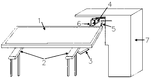
[0022] see figure 1 , the present invention provides a technical solution: a method for automatic labeling of photovoltaic modules, characterized in that: comprising the following steps:

[0023] A. Save the pre-designed nameplate templates and border barcodes for each gear in the root directory of the exclusive labeling program;

[0024] B. After the IV test, the component 1 automatically flows into the labeling station through the assembly line 2 and stops ...


PUM


Abstract

The invention discloses an automatic labeling method for photovoltaic components. The automatic labeling method comprises the following steps: (A) nameplate mold plates and frame barcodes of all pre-designed gears are stored in an exclusive labeling program root directory; (B) the components finishing IV test flow into a labeling station automatically by a production line and are fixed and stopped; (C) an automatic barcode scanning gun is automatically triggered, scans barcodes of the glass surfaces of the components, and transmits the scanned barcodes into an exclusive labeling program in a computer by a data line; (D) the exclusive labeling program automatically calls power and current data of the corresponding barcodes from a shared IV database, analyzes and judges the shifts of power and current automatically according to the data and transmits information to printers by the data line; (E) the two printers are respectively and automatically started after receiving printing commands, and print corresponding frame barcodes and nameplates. The automatic labeling method disclosed by the invention realizes full-automatic labeling operation, has higher automation degree and operationefficiency, and meanwhile has the beneficial effects that the labor can be reduced and the labor cost can be reduced.

Description

technical field [0001] The invention relates to the technical field of automatic labeling, in particular to a method for automatic labeling of photovoltaic modules. Background technique [0002] At present, in the manufacturing process of photovoltaic modules, three kinds of labels, barcodes (glass surface, backplane surface and frame barcodes), current gear label and nameplate, need to be pasted. , paste the nameplate and current gear label corresponding to the gear position, and paste the frame barcode consistent with the barcode pasted on the glass surface or back panel of the module in advance. However, the pasting methods of these three kinds of labels are manual work, which is easy Wrong nameplate (the posted nameplate does not match the actual measured power level), three different codes (the three barcodes on the glass surface, the back panel surface, and the frame are not uniform), repeated codes (the pasted barcodes have been pasted on other components), Inconsist...

Claims


Application Information

Patent Timeline
Patent Type & Authority Applications(China)
IPC IPC(8): B65C9/46B65C9/36
CPCB65C9/46B65C9/36
Inventor 马俊
Owner 格润智能光伏南通有限公司
Why Eureka
Try Eureka