Electronically controlled silicon oil fan control method and controller

A fan control and silicon oil technology, applied in the control of coolant flow, machine/engine, engine components, etc., can solve the problems that the control strategy cannot be automatically corrected and the control accuracy is not high, so as to save manpower and time costs, flexible adjustment, The effect of reducing fuel consumption

Pending Publication Date: 2018-09-11
DONGFENG BEHR THERMAL SYST
View PDF0 Cites 23 Cited by
  • Summary
  • Abstract
  • Description
  • Claims
  • Application Information

AI Technical Summary

Problems solved by technology

[0004] At present, the control strategy of the mainstream electronically controlled fan cannot be automatically corrected according to the changes in the vehicle environment and operating conditions, and its control accuracy is not high. situation, developed a control method and controller with advanced intelligent silicone oil fan

Method used


Image

  • Electronically controlled silicon oil fan control method and controller
  • Electronically controlled silicon oil fan control method and controller
  • Electronically controlled silicon oil fan control method and controller

Examples


Embodiment Construction

[0039] The present invention will be further described below in conjunction with the accompanying drawings and specific embodiments.

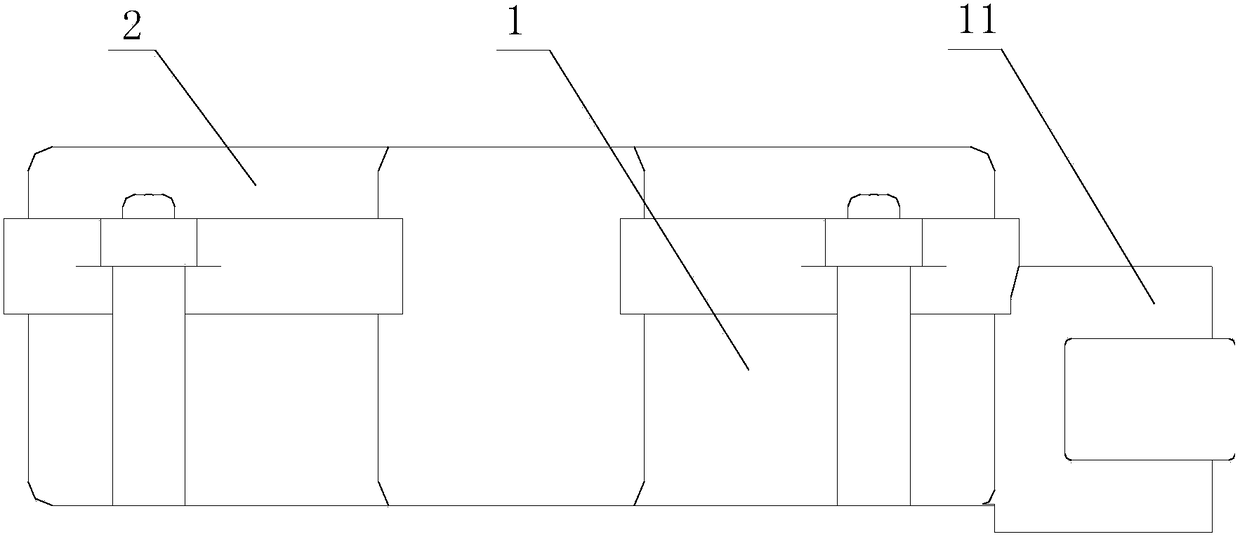
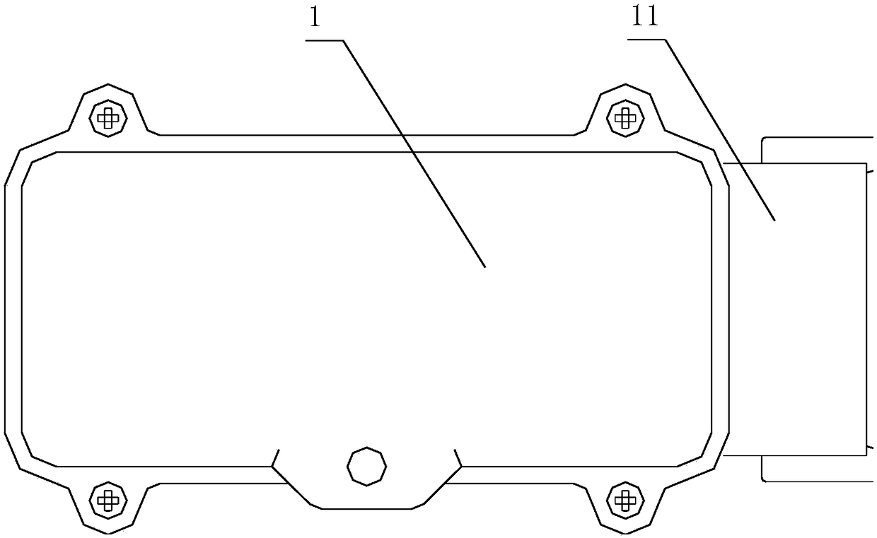
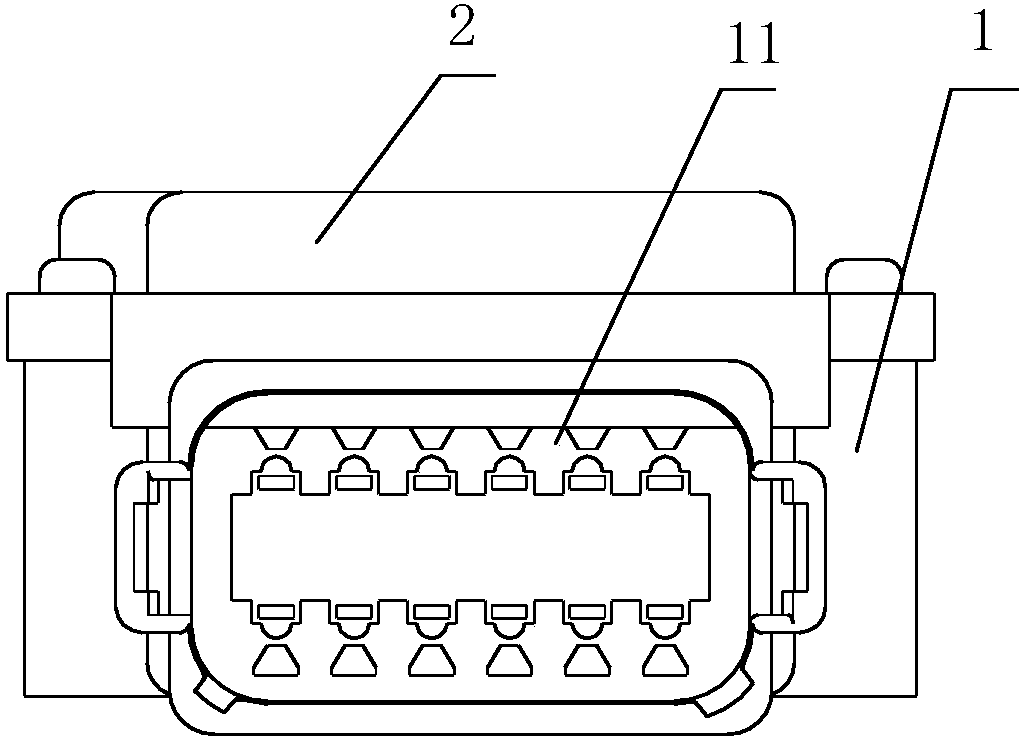
[0040] Such as Figure 1-3 As shown, an electronically controlled silicon oil fan controller of the present invention is placed in the engine compartment to intelligently adjust the speed of the silicon oil fan. The main structure of the controller includes a lower cover 1 and an upper cover 2 covered on the lower cover 1, the lower cover 1 and the upper cover 2 constitute the outer shell of the controller, between the lower cover 1 and the upper cover 2 A circuit board is installed in the inner space of the room, and a small cover plate is provided at the bottom of the socket 11 on one side of the lower cover plate 1 . The four legs of the lower cover 1 and the upper cover 2 are fixedly connected together by screws, and a sealing ring is arranged at the joint surface of the lower cover 1 and the upper cover 2 .

[0041]In this embodiment, th...


PUM


Abstract

The invention relates to an electronically controlled silicon oil fan, in particular to an electronically controlled silicon oil fan control method and a controller. The controller is arranged in an engine compartment, and a circuit board is arranged between an upper cover plate and a lower cover plate. Electrical elements arranged on the circuit board constitute a control circuit, and the controlcircuit includes a CAN acquisition circuit, an MCU integrated circuit, a power supply circuit and a PWM control circuit. The operating parameters in an ECU of a vehicle are read by the CAN acquisition circuit and sent to the MCU integrated circuit; a fan control signal is formed through the logical judgment of the collected operating parameters by the MCU integrated circuit and sent to the PWM control circuit; the PWM control circuit converts the received fan control signal into a PWM signal to be used for controlling the rotation speed of a fan; and the actual rotation speed value of the fanis dynamically controlled by reading the collected real-time operating parameters of the vehicle.

Description

technical field [0001] The invention relates to an electronically controlled silicon oil fan, in particular to a control method and a controller for an electronically controlled silicon oil fan. Background technique [0002] During the driving process of the car, as the operating environment and working conditions change, the thermal state of the engine is also constantly changing. In order to ensure normal driving, it is necessary to adjust the thermal state of the engine in real time. For example, in hot summer, when the engine works at low speed and heavy load for a long time, the temperature of the engine is high. At this time, we should actively reduce its temperature; When the temperature of the engine is low, we should increase its temperature at this time. [0003] At present, the heat dissipation of the engine in commercial vehicles is mainly carried out by silicon oil fans. Silicon oil fans use silicone oil as a medium to transmit torque and then drive the fan to ...

Claims


Application Information

Patent Timeline
Patent Type & Authority Applications(China)
IPC IPC(8): F01P7/04
CPCF01P7/048F01P2050/22
Inventor 彭斯李东平都英
Owner DONGFENG BEHR THERMAL SYST
Why Eureka
Try Eureka