
Combined dehumidifier in subway station and dehumidification method and application thereof

A subway station, combined technology, applied in the field of dehumidification, can solve the problems of the ventilation and air conditioning system not being put into operation, the working environment is bad, the work efficiency is low, etc., and the effect of improving the dehumidification efficiency, small size and reducing the consumption of electric energy is achieved.

Pending Publication Date: 2018-09-11
中交二公局铁路建设有限公司
View PDF6 Cites 4 Cited by
  • Summary
  • Abstract
  • Description
  • Claims
  • Application Information

AI Technical Summary

Problems solved by technology

However, during the construction process, all majors are in the construction and installation stage, and the ventilation and air conditioning system has not been put into operation. During the construction stage, only simple ventilation methods can be used to allow the air in the station to circulate to achieve the purpose of dehumidification
However, when the outdoor weather conditions are "high temperature and high humidity" in summer, the simple ventilation and dehumidification method has no obvious effect on the leakage of the civil structure and the condensation on the wall surface of the station. The accumulated water on the ground is removed. This method has harsh working environment, high labor intensity, and low work efficiency. It cannot fundamentally solve the problem of humid environment in the subway station.

Method used


Image

  • Combined dehumidifier in subway station and dehumidification method and application thereof
  • Combined dehumidifier in subway station and dehumidification method and application thereof

Examples


Embodiment 1

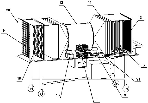
[0039] This embodiment provides a combined dehumidification device in a subway station, such as figure 1 Shown, including a mobile trolley, the mobile trolley is installed with a fan 12, the air inlet end of the fan 12 is connected to the freezing dehumidification system, the entrance of the freezing dehumidification system is installed with an electrostatic precipitator 2, and the air supply end of the fan 12 is connected With heating and dehumidification system.

[0040] The working process of the combined dehumidification device in the subway station is as follows:

[0041] During the construction phase in the subway station, move the combined dehumidification device in the subway station to the construction area with high moisture content, so that the combined dehumidification device in the subway station and the exhaust fans at the two ends of the station form convection, and the fans 12, static electricity are connected Dust collector 2, freezing dehumidification system, heat...

Embodiment 2

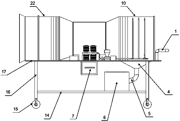
[0044] On the basis of Example 1, such as figure 2 As shown, the freezing and dehumidifying system is composed of a circulating copper pipe 3, a variable diameter deflector 4, a deflector pipe 5, a water collecting tank 6, a circulating water pump 8, a semiconductor refrigerator 9, an air inlet pipe 10 and a water tank 21;

[0045] One end of the air inlet pipe 10 is connected to the air inlet end of the fan 12, the electrostatic precipitator 2 is installed at the other end of the air inlet pipe 10, the circulating copper pipe 3 is vertically installed in the air inlet pipe 10 in an S shape, and the circulating copper One end of the tube 3 is connected to the semiconductor refrigerator 9 and the other end is connected to the circulating water pump 8. The water tank 21 is connected between the semiconductor refrigerator 9 and the circulating water pump 8. The circulating copper pipe 3, the semiconductor refrigerator 9, the water tank 21, and the circulating water pump 8 form a cir...

Embodiment 3

[0049] On the basis of Example 2, the variable diameter deflector 4 is a bucket-shaped structure, the large-diameter end of the bucket-shaped structure is connected to the opening opened on the bottom surface of the air inlet pipe 10, and the small-diameter end is connected to the guide pipe 5.

[0050] Such as figure 1 with figure 2 As shown, the bottom surface of the air inlet pipe 10 is open, and the large-diameter end of the variable-diameter deflector 4 has the same size as the opening, and the two are connected, and the variable-diameter deflector 4 gradually shrinks from the large diameter to the small diameter. , The small diameter is the same as the diameter of the diversion pipe 5, and the two are connected. The diversion pipe 5 extends into the water collection tank 6. When the combined dehumidification device in the subway station is working, condensation occurs and the water condensed and precipitated is moved along under the action of gravity. The annular copper pi...


PUM


Abstract

The invention provides a combined dehumidifier in a subway station and a dehumidification method and application of the combined dehumidifier. The dehumidifier comprises a mobile trolley, the mobile trolley is provided with a draught fan, the air feeding end of the draught fan is connected with a refrigerating and dehumidification system, an inlet of the refrigerating and dehumidification system is provided with an electrostatic dust collector, and the air sending end of the draught fan is connected with a temperature-raising and dehumidification system. Three dehumidification methods including refrigerating dehumidification, temperature-raising dehumidification and ventilating dehumidification are adopted simultaneously, the moisture content of the air in the subway station can be loweredrapidly, dehumidification efficiency is improved, safe operation and construction quality of all professional electrical equipment are guaranteed, and a safe and good construction environment is provided for workers. The combined dehumidifier in the subway station is used for dehumidification of a construction work area in the subway station, and when the combined dehumidifier is applied, a convection current is formed between the draught fan of the combined dehumidifier in the subway station and exhaust fans at wind gaps of the two ends of the subway station.

Description

Technical field [0001] The invention belongs to the field of dehumidification technology, and specifically relates to a combined dehumidification device in a subway station and a dehumidification method and application thereof, and is particularly suitable for dehumidification in a construction operation environment with a large moisture content in a subway station. Background technique [0002] A humid construction environment in subway stations has always been a serious problem. The main reason is that subway projects are generally underground. There are many professional cross-operations in the construction stage, the use of construction water is large, the air circulation is not smooth, and the source of moisture is extensive. During the construction phase, the composition of the wet load in the subway station is very complex, mainly including the leakage of the enclosure structure, the exchange of the air wet load at the entrance and exit, the outdoor fresh rheumatic load, an...

Claims


Application Information

Patent Timeline
Patent Type & Authority Applications(China)
IPC IPC(8): F24F3/14F25B21/02
CPCF24F3/147F25B21/02F24F2003/1446
Inventor 佘刚宏杨楠秦浩秦伊佐张忠瑜车永富王蒙
Owner 中交二公局铁路建设有限公司
Learn More