Novel converter for metal smelting

A new type of metal smelting technology, applied in the field of new metal smelting converters, can solve the problems of fuel consumption, limited and serious air feeding, and achieve the effects of increasing heating speed, enhancing combustion effect, and enhancing combustion temperature.

Inactive Publication Date: 2018-09-11
CHENGDU JUNSHUO RUIZHI INFORMATION TECH CO LTD
View PDF0 Cites 0 Cited by
  • Summary
  • Abstract
  • Description
  • Claims
  • Application Information

AI Technical Summary

Problems solved by technology

[0002] The converter is a tool used in the metal smelting process. The traditional rotary converter usually rotates around the axis of its furnace body. In its furnace, sufficient air is continuously supplied to the fuel to meet the high temperature heating requirements for various metal materials. Furnace temperature requirements, but the air used in the work of the widely used rotary converter is fed into the converter from the bottom of the converter through pipes. There are two problems in this way. Insufficient contact with the supplied air can not give full play to the heat released by fuel combustion, so that the heating speed of metal material parts is slow, resulting in longer heating time of objects, more serious fuel consumption, and increased production cost burden; 2. It is the residue produced by fuel combustion that easily blocks the air inlet pipe and prevents the outside air from entering the converter, making the fuel and air not in sufficient contact and affecting the normal operation of the converter

Method used


Image

  • Novel converter for metal smelting
  • Novel converter for metal smelting
  • Novel converter for metal smelting

Examples


Embodiment 1

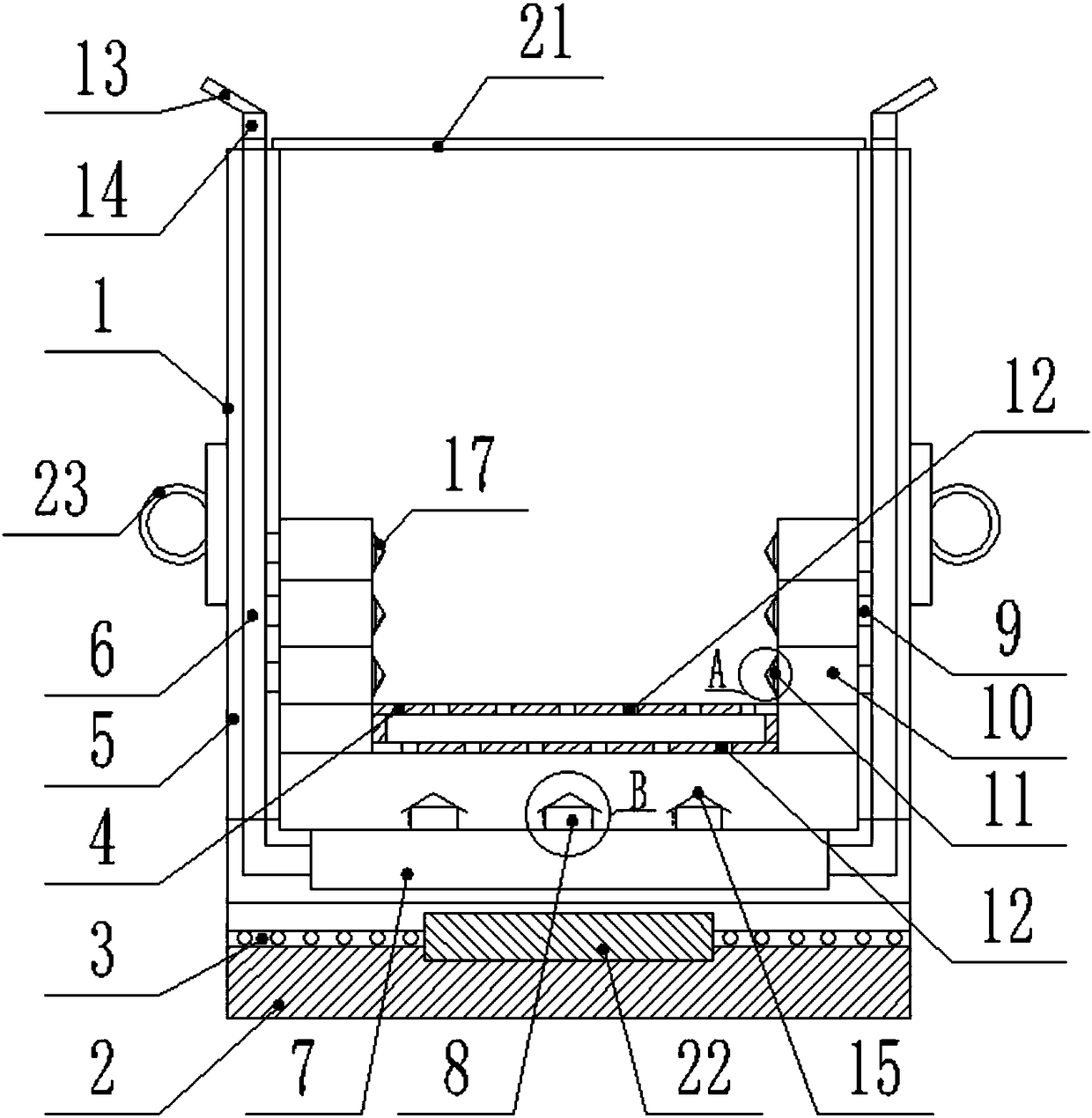
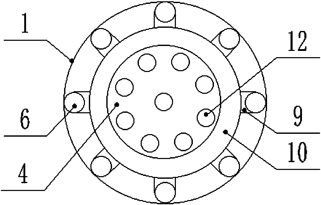
[0033] Such as Figure 1-4As shown, a new converter for metal smelting includes a furnace body 1 and a furnace base 2, the furnace body 1 and the furnace base 2 are connected by a bearing 3, and a positioning shaft 22 is arranged between the furnace body 1 and the base The bottom of the furnace body 1 and the top of the furnace base 2 are respectively provided with grooves matched with the positioning shaft 22, and the positioning shaft 22 is arranged on the groove at the bottom of the furnace body 1 and the concave groove on the top of the furnace base 2. in the space formed by the groove. The positioning shaft 22 makes the furnace body 1 more stable when rotating on the furnace base 2 . The furnace body 1 is provided with a ventilation assembly and a combustion rack 4 for placing fuel; the side wall of the furnace body 1 is provided with several cavities 5; the top of the furnace body 1 is provided with a furnace cover 21, The furnace cover 21 is movably connected with the...

Embodiment 2

[0042] Such as Figure 1-4 As shown, this implementation is further optimized on the basis of Embodiment 1. This embodiment focuses on the improvements compared with Embodiment 1, and the similarities will not be repeated. In this embodiment, the first output The outlet end of the air duct 8 is provided with a first baffle plate 15 with a herringbone cross section, the top of the first air outlet duct 8 is embedded between the first baffle plates 15, and the side of the first air outlet duct 8 The wall is provided with a through first ventilation hole 16 . The air can escape from the first ventilation hole 16 and will not be blocked by residues on the air guide pipe 6 pipes. The first baffle plate 15 can solve the problem that the residue generated by fuel combustion blocks the air guide pipe 6 pipes and prevents the outside air from entering the air guide pipe 6. In the converter, the fuel is not in sufficient contact with the air, which affects the normal operation of the c...

Embodiment 3

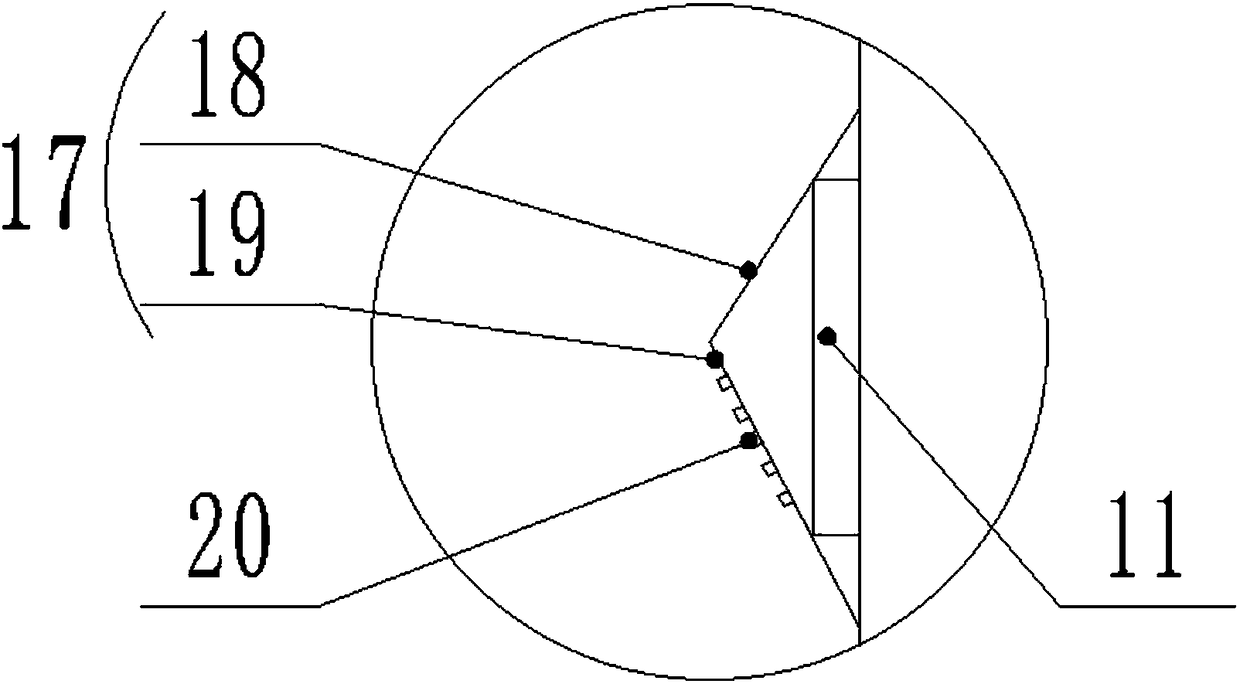
[0044] Such as Figure 1-4 As shown, this implementation is further optimized on the basis of Embodiment 1. This embodiment focuses on the improvements compared with Embodiment 1, and the similarities will not be repeated. In this embodiment, the second output The outlet end of air duct 11 is provided with the second baffle plate 17 that cross-section is herringbone, and described second baffle plate 17 is made up of upper baffle plate 18 and lower baffle plate 19, and the upper baffle plate 18 and lower baffle plate 19 One end is connected, and the other ends of the upper baffle plate 18 and the lower baffle plate 19 are respectively connected with the side walls of the ventilation chamber 10 , and the lower baffle plate 19 is provided with a plurality of second ventilation holes 20 . The second ventilation hole 20 on the lower baffle plate 19 can diffuse the air in the ventilation chamber 10 into the body of heater 1, so that the fuel in the burning state on the combustion r...


PUM


Abstract

The invention discloses a novel converter for metal smelting, and belongs to the technical field of metal smelting. The novel converter is used for solving the problems that air introduction for an existing converter is insufficient and residue is likely to block vent holes. The novel converter comprises a converter body and a converter base, the converter body and the converter base are connectedthrough a bearing, a ventilation assembly and a combustion frame where fuel is placed are arranged in the converter body, the side wall of the converter body is provided with a plurality of cavities,an air guide assembly comprises an air guide pipe, an air collection chamber and the ventilation assembly, the air guide pipe penetrates through the cavity to be distributed inside the converter bodyin a circumference shape, the top end of the air guide pipe is arranged outside the converter body, the bottom end of the air guide pipe communicates with the air collection chamber, the air collection chamber is arranged at the bottom of the converter body, the top of the air collection chamber is provided with a plurality of first air outlet pipes, the ventilation assembly comprises a ventilation pipe and a ventilation chamber, the ventilation pipe is distributed between the air guide pipe and the ventilation chamber in a circumference shape, one end of the ventilation pipe communicates with the air guide pipe, the other end of the ventilation pipe communicates with the ventilation chamber, and the end, close to the axis center, of the ventilation chamber is provided with a second air outlet pipe.

Description

technical field [0001] The invention relates to the technical field of metal smelting, in particular to a novel converter for metal smelting. Background technique [0002] The converter is a tool used in the metal smelting process. The traditional rotary converter usually rotates around the axis of its furnace body. In its furnace, sufficient air is continuously supplied to the fuel to meet the high temperature heating requirements for various metal materials. Furnace temperature requirements, but the air used in the work of the widely used rotary converter is fed into the converter from the bottom of the converter through pipes. There are two problems in this way. Insufficient contact with the supplied air can not give full play to the heat released by fuel combustion, so that the heating speed of metal material parts is slow, resulting in longer heating time of objects, more serious fuel consumption, and increased production cost burden; 2. It is the residue produced by f...

Claims


Application Information

Patent Timeline
Patent Type & Authority Applications(China)
IPC IPC(8): F27B7/00F27B7/20
Inventor 张德彬
Owner CHENGDU JUNSHUO RUIZHI INFORMATION TECH CO LTD
Why Eureka
Try Eureka