High-precision probe device used for linearity error measurement

A straightness error and high-precision technology, which is applied in the field of high-precision measuring head devices, can solve the problems of low measurement accuracy and high manufacturing cost, and achieve the effects of improving motion stability, improving motion stability, and reducing dynamic and static friction coefficients

Active Publication Date: 2018-09-11
DALIAN UNIV OF TECH
View PDF4 Cites 5 Cited by
  • Summary
  • Abstract
  • Description
  • Claims
  • Application Information

AI Technical Summary

Problems solved by technology

[0005] In order to solve the problem of low measurement accuracy and high manufacturing cost of the existing probe guide rail system, the present invention provides a high-precision straightness error probe device without measuring Abbe errors

Method used


Image

  • High-precision probe device used for linearity error measurement
  • High-precision probe device used for linearity error measurement
  • High-precision probe device used for linearity error measurement

Examples


Embodiment Construction

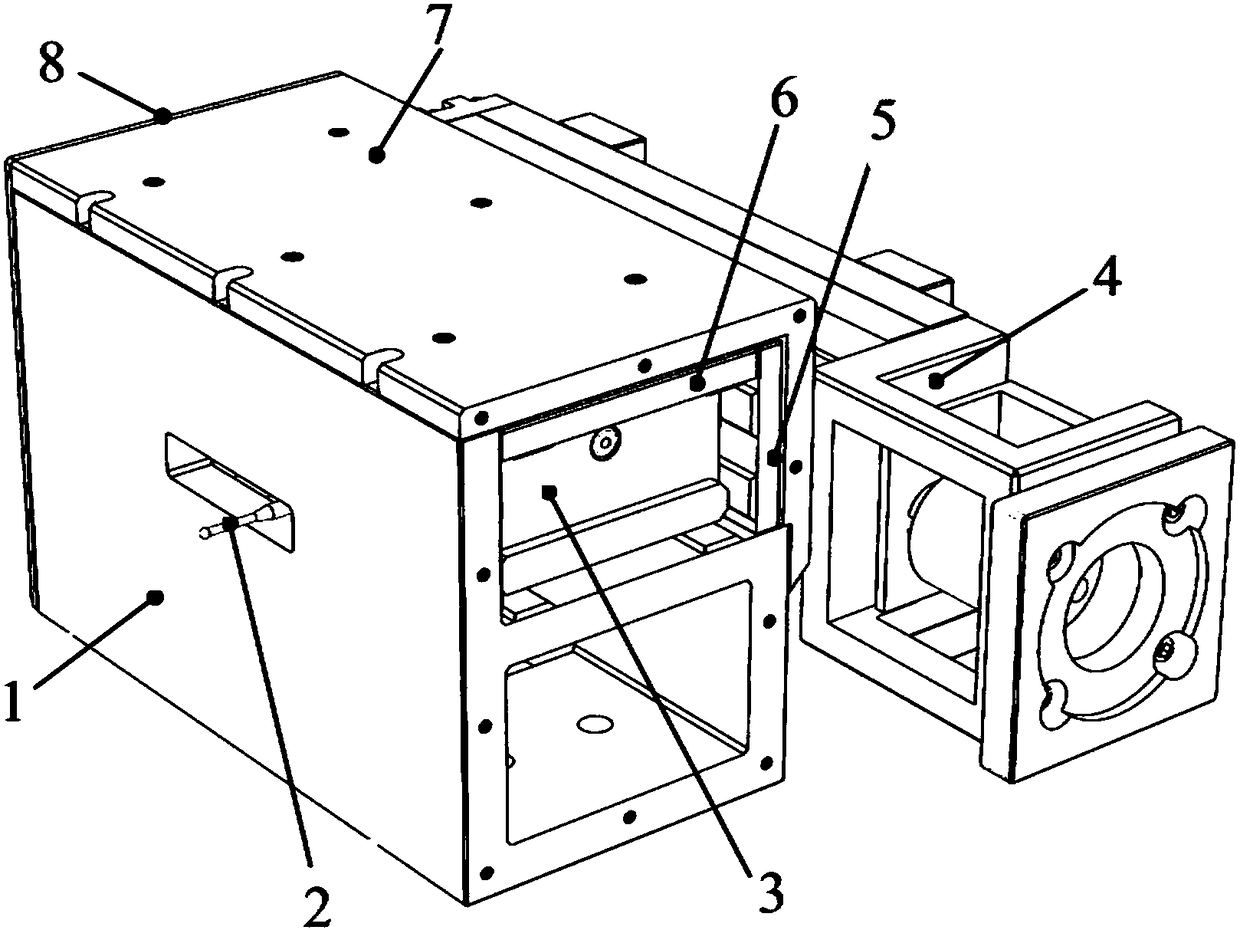
[0024] Taking the measurement of the helical deviation of a straight-toothed standard gear with grade 1 precision as an example, the specific implementation of the high-precision measuring head device proposed by the invention is described.

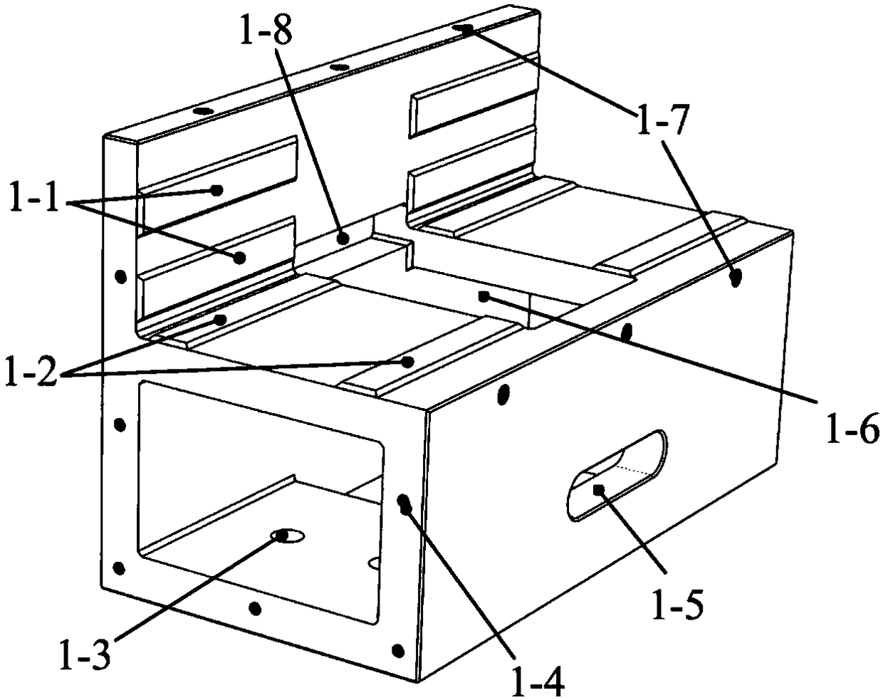
[0025] (1) Machining accuracy of key components.

[0026] The horizontal working surface 1-2 of the guide rail seat 1, the vertical working surface 1-1, each working surface 3-2-1 of the slide block 3-23 pasted with the PTFE guide rail soft belt, the upper pressing plate 6 and the side pressing plate 5 The flatness error of the working surface is not greater than 1 μm, and the flatness error of the horizontal plane 1-2 of the guide rail seat used as the probe reference is not greater than 0.5 μm;

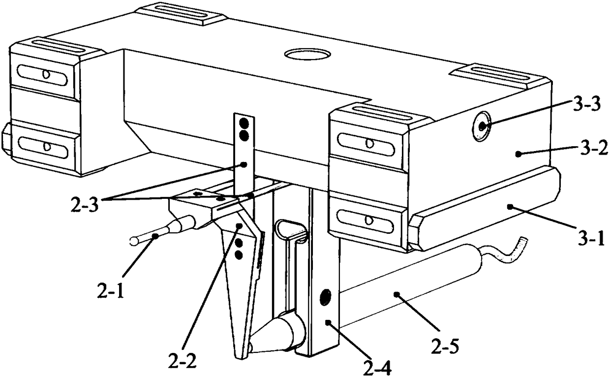
[0027] After the slider 3-2 is pasted with the PTFE guide rail soft belt, the distance error of the relatively parallel slider working surface is not more than 1 μm; after the slider is attached to the horizontal working surface 1-2 of the guid...


PUM


Abstract

The invention belongs to the technical field of precision machining and testing, and discloses a high-precision probe device used for linearity error measurement. The device comprises a guide seat, amicro-displacement lever transmission system, a slide block system, a slide block driving system, a side pressure plate, an upper pressure plate, a cover plate, and a side baffle. According to the device, a polytetrafluoroethylene guide rail soft tape is adopted as a friction auxiliary material, and the motion stationarity of a slide block and a probe can be substantially improved in a lubricationstate; the position of a measuring point is located above an extending surface of a guide rail work surface so that the direction has no measuring Abbe error, and the measuring precision can reach the submicron magnitude; by employing a high-sensitivity crossed reed micro-displacement transmission lever, the micro-displacement acquired by a ball probe is transmitted to a high-precision inductionprobe in an equivalent manner, and the device is applicable to the measurement of high-precision linearity errors without direct adoption of an axial probe. The device is advantageous in that the structure is simple, the deformation is symmetric, the influence of the driving precision on the motion precision of the probe is small, measuring Abbe errors can be avoided, the measuring precision of linearity errors is high, and the application range is wide.

Description

technical field [0001] The invention belongs to the technical field of precision machining and testing, and relates to a high-precision measuring head device for straightness error measurement. Background technique [0002] Straightness error is a very common form and position tolerance. According to the continuity of measurement, the methods of measuring straightness error include continuous measurement method and single-point multiple measurement method; according to the number of data acquisition directions, it is divided into single-degree-of-freedom measurement and double-degree-of-freedom measurement. Among them, the single-degree-of-freedom straightness measurement is the most widely used. It is not only suitable for the measurement of any straight line on the plane, but also suitable for the measurement of the rotary body and the ruled surface whose generatrix is ​​a straight line. To ensure the measurement accuracy of the straightness meter, it is necessary to ensu...

Claims


Application Information

Patent Timeline
Patent Type & Authority Applications(China)
IPC IPC(8): G01B7/31
CPCG01B7/31
Inventor 凌四营李军于宝地陈义磊汪训练王立鼎
Owner DALIAN UNIV OF TECH
Why Eureka
Try Eureka