
Multi-light source phase sensitive light time domain reflectometer and method thereof

A technology of phase-sensitive optical time-domain reflectometer, applied in the direction of utilizing wave/particle radiation, measuring devices, instruments, etc., can solve the problems of low frequency response and polarization fading of phase-sensitive optical time-domain reflectometer

Pending Publication Date: 2018-09-11
ZHEJIANG JERICORE TECH CO LTD
View PDF2 Cites 10 Cited by
  • Summary
  • Abstract
  • Description
  • Claims
  • Application Information

AI Technical Summary

Problems solved by technology

[0010] An object of the present invention is to provide a multi-light source phase-sensitive optical time-domain reflectometer and its method, which overcomes the adverse effects of interference fading on detection, enhances the anti-polarization fading characteristics of the system, and solves the problem of phase-sensitive optical time-domain reflection The Problem of Polarization Fading in Meters
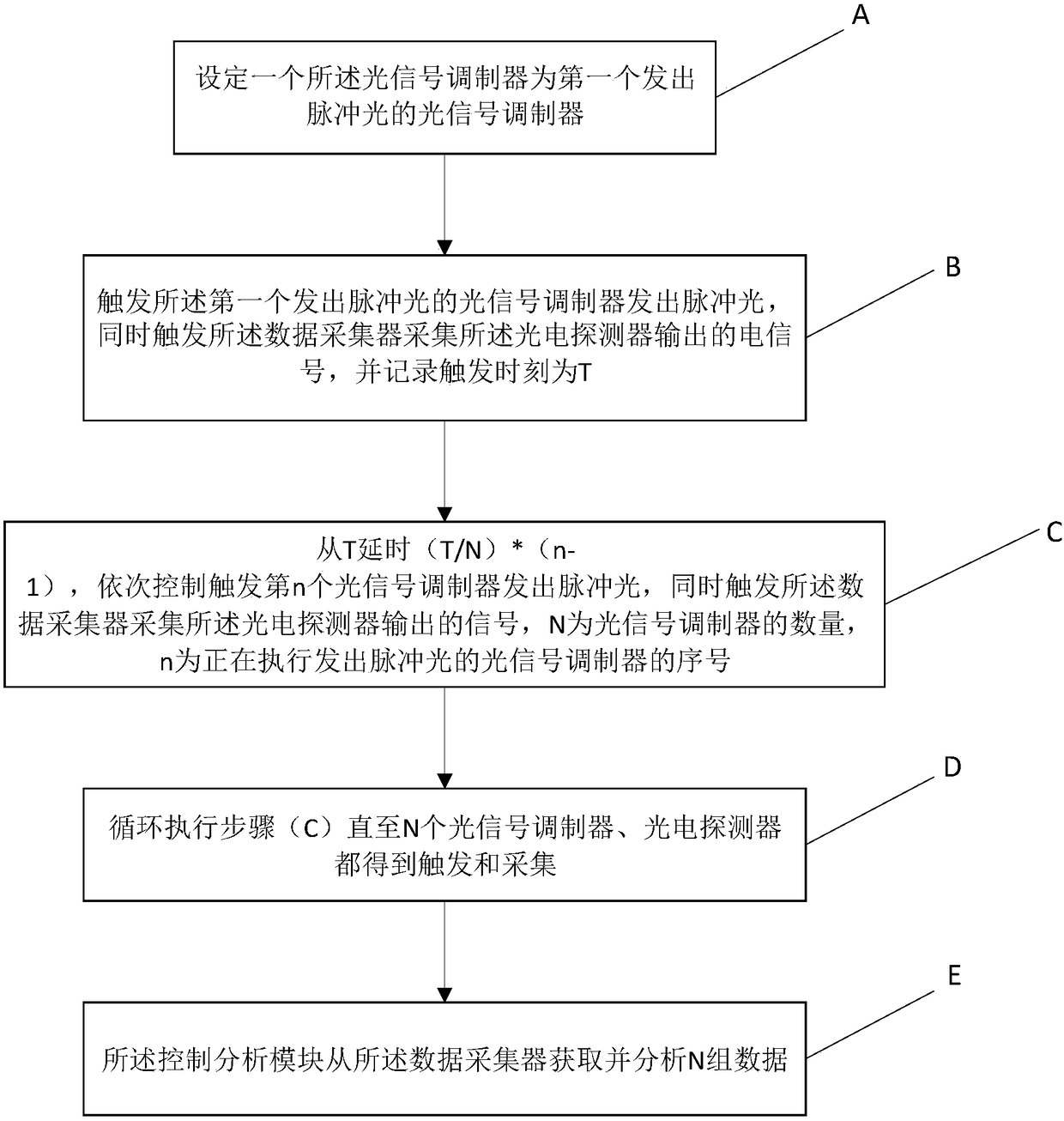
[0011] Another object of the present invention is to provide a multi-light source phase-sensitive optical time-domain reflectometer and its method. By controlling the triggering moment of the optical signal modulator and increasing the number of measurements of the same point in space, the phase-sensitive optical time-domain reflectometer is improved. The frequency response range of the reflectometer solves the problem of low frequency response of the phase-sensitive optical time domain reflectometer

Method used


Image

  • Multi-light source phase sensitive light time domain reflectometer and method thereof
  • Multi-light source phase sensitive light time domain reflectometer and method thereof
  • Multi-light source phase sensitive light time domain reflectometer and method thereof

Examples


Embodiment Construction

[0039] Below, the invention will be further described in conjunction with the accompanying drawings and specific implementation methods. It should be noted that, on the premise of no conflict, the various embodiments described below or the technical features can be combined arbitrarily to form a new embodiment. .

[0040] The following description serves to disclose the present invention to enable those skilled in the art to carry out the present invention. The preferred embodiments described below are only examples, and those skilled in the art can devise other obvious variations. The basic principles of the present invention defined in the following description can be applied to other embodiments, variations, improvements, equivalents and other technical solutions without departing from the spirit and scope of the present invention.

[0041] Those skilled in the art should understand that in the disclosure of the present invention, the terms "vertical", "transverse", "upper...


PUM


Abstract

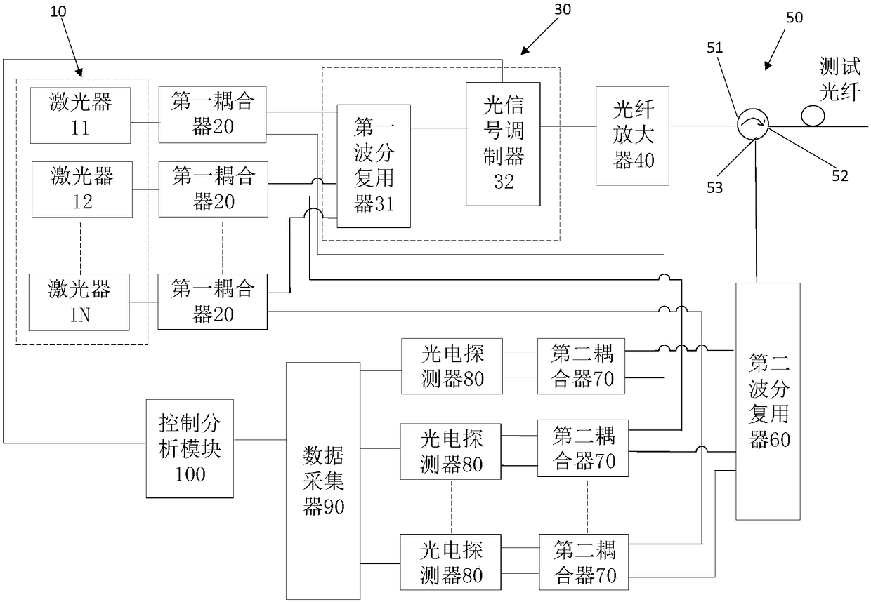
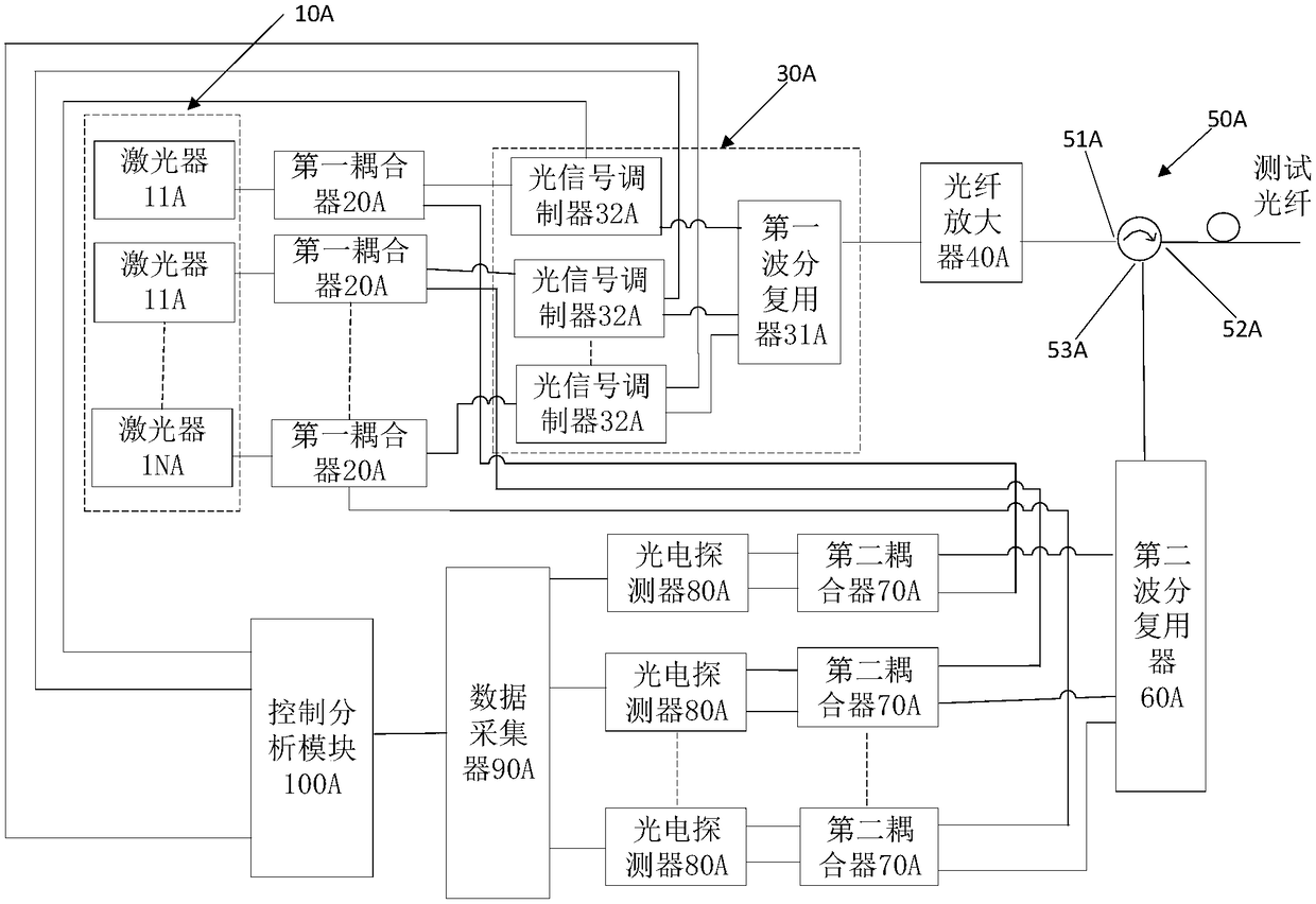
The invention discloses a multi-light source phase sensitive light time domain reflectometer and a method thereof. The reflectometer includes a plurality of lasers, multiple first couplers, multiple second couplers and multiple photodetectors. Continuous light emitted from the different lasers are different in wavelengths. The continuous light emitted from the lasers is shunted through the first couplers to the second couplers and a wavelength division multiplexing modulation module. The wavelength division multiplexing modulation module modulates the multi-channel continuous light into pulsedlight, combines the pulsed light into one channel light, outputs the one channel light to a fiber amplifier, and then outputs the amplified light to a three-port circulator. A second wavelength division multiplexer inputs backward Rayleigh scattering light of different wavelengths to the second couplers with the same wavelength continuous light for interference. The photodetectors convert the multi-channel interference light signals into electric signals and transmit the signals to a data collector and a control analysis module to obtain sensing information of a fiber. Through adoption of theplurality of lasers different in wavelength and the plurality of photodetectors, the anti-polarization fading characteristics of the system are improved.

Description

technical field [0001] The invention relates to the technical field of distributed optical fiber vibration sensors, and more specifically relates to a multi-light source phase-sensitive optical time-domain reflectometer and a method thereof. Background technique [0002] The optical time domain reflectometer (OTDR) uses the Rayleigh scattered light generated when the pulsed light propagates in the optical fiber to obtain attenuation information, which is an indispensable tool for optical cable construction and monitoring. However, because the traditional OTDR uses a low-coherence broadband light source, it can only detect changes in light intensity information in Rayleigh scattered light, so it can only realize functions such as fiber length, fiber attenuation, and fiber fault location. In 1993, H.F.Taylor et al proposed the phase-sensitive optical time-domain reflectometry (φ-OTDR). The change of the light intensity information in the scattered light can be used, and the c...

Claims


Application Information

Patent Timeline
IPC IPC(8): G01H9/00
CPCG01H9/004
Inventor 刘航杰谢怡敏胡逸波
Owner ZHEJIANG JERICORE TECH CO LTD
Learn More