Integrated optical mode switch compatible with wavelength division multiplexing function and mode division multiplexing function

A mode division multiplexing and division multiplexing technology, applied in the direction of light guides, optics, optical components, etc., can solve the problems of low cost, inability to connect freely, and equal quantity, so as to improve flexibility and survivability, save upgrade costs, The effect of a simple structure

Active Publication Date: 2018-09-11
LANZHOU UNIVERSITY
View PDF4 Cites 8 Cited by
  • Summary
  • Abstract
  • Description
  • Claims
  • Application Information

AI Technical Summary

Problems solved by technology

[0005] The purpose of the present invention is to provide an integrated optical mode switch compatible with wavelength division multiplexing and mode division multiplexing to solve the problems that the number of input terminals and receiv

Method used


Image

  • Integrated optical mode switch compatible with wavelength division multiplexing function and mode division multiplexing function
  • Integrated optical mode switch compatible with wavelength division multiplexing function and mode division multiplexing function
  • Integrated optical mode switch compatible with wavelength division multiplexing function and mode division multiplexing function

Examples


Embodiment Construction

[0019] The present invention will be described in detail below in conjunction with the accompanying drawings and specific embodiments.

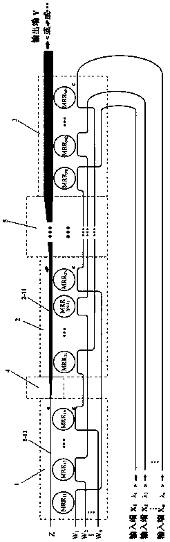
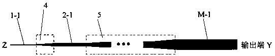
[0020] Such as figure 1 As shown, the optical mode switch of the present invention includes a plurality of multiplexing units arranged in sequence, and two adjacent multiplexing units are connected through an adiabatic cone, such as: the adjacent first multiplexing unit 1 and the second multiplexing unit The units 2 are connected through the first adiabatic cone 4 , and the adjacent M-1th multiplex unit and the M-th multiplex unit 3 are connected through the M-1th adiabatic cone 5 . Wherein M is any positive integer. The first multiplexing unit 1 is a basic mode multiplexing unit, and the other multiplexing units are high-order mode multiplexing units.

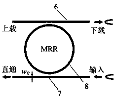
[0021] The first multiplexing unit 1 in the optical mode switch of the present invention is composed of multiple (N, N is any positive integer) sequentially connected microring resonators. ...


PUM


Abstract

The invention relates to an integrated optical mode switch compatible with a wavelength division multiplexing function and a mode division multiplexing function. The integrated optical mode switch comprises a plurality of multiplexing units arranged sequentially; every two adjacent multiplexing units are connected together through an adiabatic cone; the multiplexing unit is composed of a pluralityof micro-ring resonators which are connected with one another sequentially; the micro-ring resonator comprises a first straight waveguide and a second straight waveguide which are arranged in parallel; a nano-silicon-based nanowire micro-ring is arranged between the two straight waveguides; the first straight waveguides of two adjacent micro-ring resonators in the same multiplexing unit are connected with one another; all the first straight waveguides in the same multiplexing unit are connected with one another so as to form a first output waveguide; and the first output waveguide of one multiplexing unit is connected with an output waveguide in a multiplexing unit adjacent to the multiplexing unit. With the optical mode switch adopted, the multiplexing of M modes and N wavelengths can berealized, and the mode of each input end, which is multiplexed into a trunk waveguide, can be freely selected and dynamically switched, so that the number of input ends and output ends in a mode division multiplexing system can be freely allocated, and the paths of the mode division multiplexing system can be selected freely.

Description

technical field [0001] The invention belongs to the technical field of optical mode multiplexing and demultiplexing, and relates to a silicon-based integrated optical mode processing device, in particular to an integrated optical mode switch compatible with wavelength division multiplexing and mode division multiplexing functions. Background technique [0002] With the rapid development of economy and society, people's demand for large-capacity, high-speed information processing and communication technology is increasing day by day. As the most critical technology in the field of communication, integrated circuit technology has ensured that the information processing needs of the past fifty years can be met. However, the further reduction of device feature size in existing integrated circuits is limited by factors such as tunnel leakage current effects, heat dissipation, and non-linear cost increases, making it difficult for integrated circuits to continue to develop at the ...

Claims


Application Information

Patent Timeline
IPC IPC(8): G02B6/293
CPCG02B6/29343
Inventor 田永辉肖恢芙刘子龙韩旭陈文平赵婷廖苗苗
Owner LANZHOU UNIVERSITY
Why Eureka
Try Eureka