Double-ridge rectangular waveguide staggered transmission line

A rectangular waveguide and transmission line technology, applied in the field of compact electromagnetic wave structure, can solve the problems of narrow bandwidth, complex matching circuit structure, large volume, etc., and achieve the effect of improving modeling optimization calculation efficiency and obvious advantages

Inactive Publication Date: 2018-09-11
成都锐烽特科技有限公司
View PDF3 Cites 0 Cited by
  • Summary
  • Abstract
  • Description
  • Claims
  • Application Information

AI Technical Summary

Problems solved by technology

[0003] The existing matching circuit has complex structure, large volume, and narrow bandwidth, especially in rectangular waveguides, single-ridge rectangular waveguides, double-ridge rectangular waveguides and four-ridge rectangular waveguides, circular waveguides or elliptical waveguides, single-ridge circular waveguides or elliptical waveguides, In the dislocation connection of double-ridge circular waveguide or elliptical waveguide, and four-ridge circular waveguide or elliptical waveguide

Method used


Image

  • Double-ridge rectangular waveguide staggered transmission line
  • Double-ridge rectangular waveguide staggered transmission line
  • Double-ridge rectangular waveguide staggered transmission line

Examples


Embodiment 1

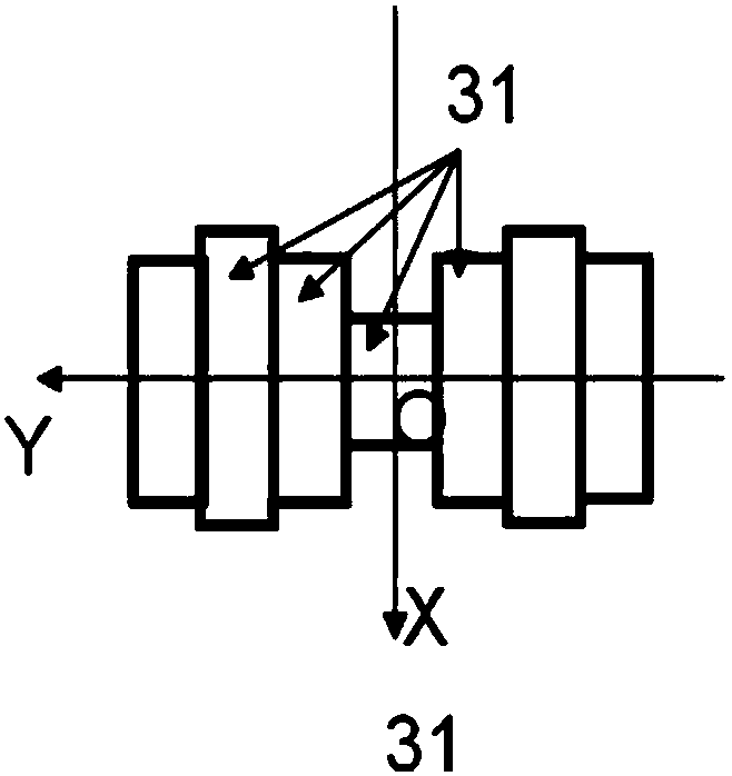
[0033] Such as Figure 1a with Figure 1b shown.

[0034] A double-ridge rectangular waveguide dislocation transmission line, comprising two transmission lines 2 and an electromagnetic channel 3; the two end faces of the electromagnetic channel 3 are respectively a part of a plane A and a plane B; the two input transmission lines 2 respectively pass through a cut surface thereof and One of the two end faces of the electromagnetic channel 3 is connected; the electromagnetic channel 3 is formed by a branch, and the electromagnetic wave branch is formed by seven through holes 31 connected along the Y direction.

[0035] The maximum length t of the electromagnetic channel is less than 0.2 times the wavelength in free space corresponding to the central operating frequency of the dislocation transmission line.

[0036] The axes of the two transmission lines 2 are staggered in the X direction of their cross sections by a distance greater than 1 / 20 of the maximum dimension of any one...

Embodiment 2

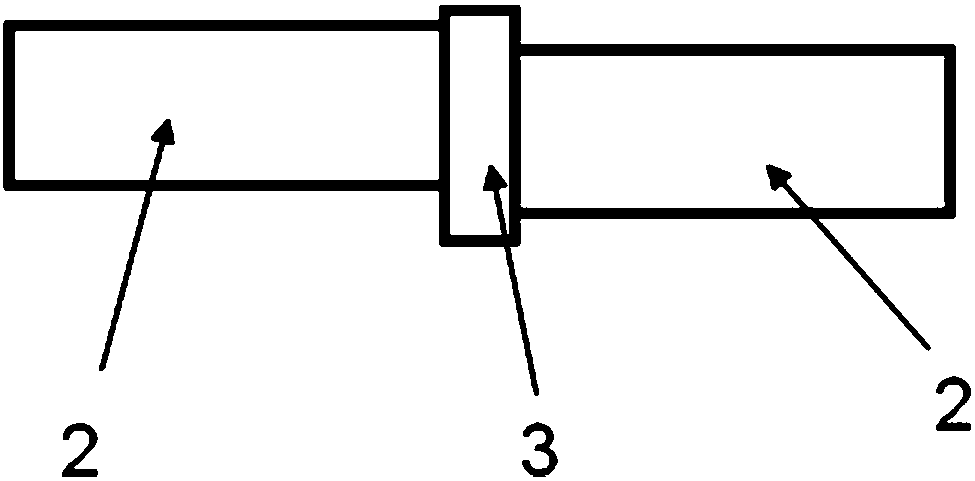
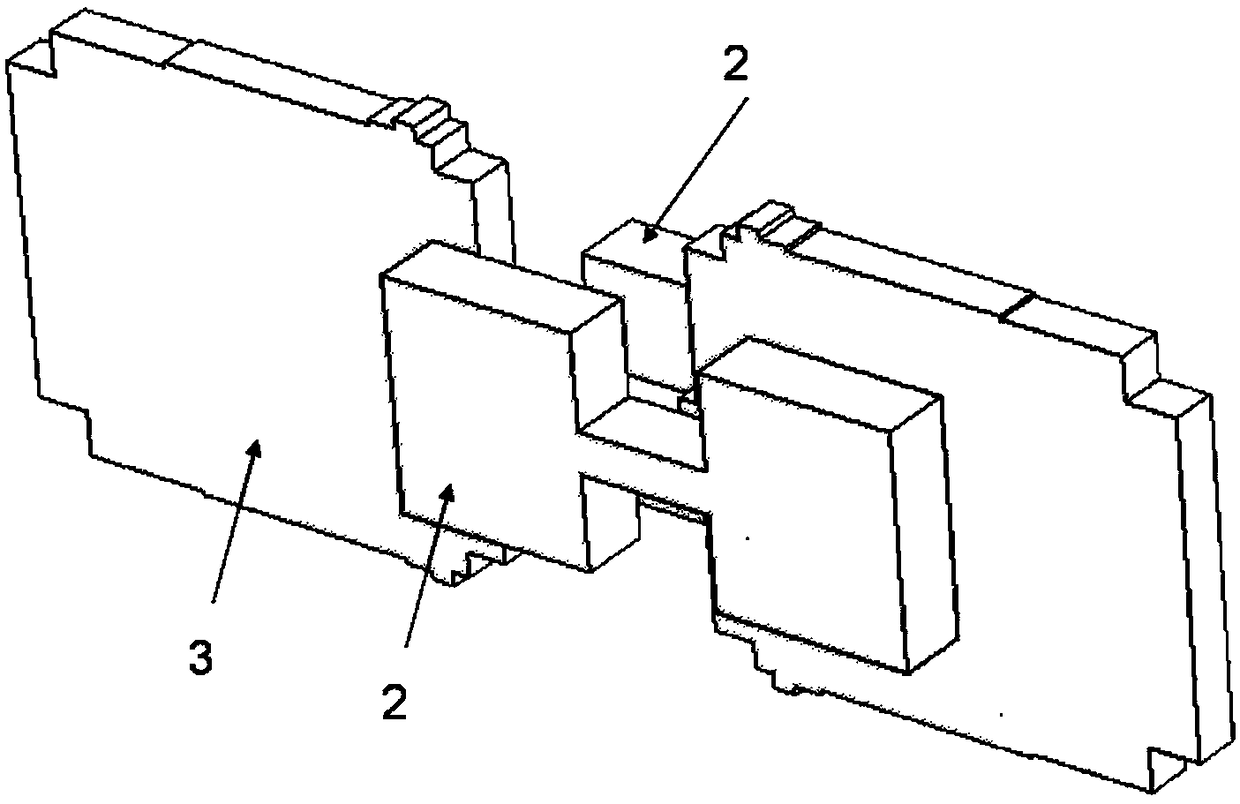
[0044] Such as figure 2 with 3 shown.

[0045] Compared with Embodiment 1, the only difference is that the two transmission lines are both double-ridge waveguides. The two transmission lines are staggered by 3 mm along the X direction. The double-ridge rectangular waveguide has a width of 7.7 mm and a height of 3.3 mm. The metal ridge width is 1.93 mm. The gap between the tops of the metal ridges is 0.61 mm. Using a length of only 0.66 mm as Figure 4 The electromagnetic channel shown has a maximum reflection coefficient of -18dB within the working bandwidth of 15-45GHz.

Embodiment 3

[0047] Such as Figure 4 with 5 shown.

[0048] Compared with Embodiment 1, the only difference is that the two transmission lines are both double-ridge waveguides. The two transmission lines are staggered by 0.75 mm along the Y direction. The double-ridge rectangular waveguide has a width of 7.7 mm and a height of 3.3 mm. The metal ridge width is 1.93mm. The gap between the tops of the metal ridges is 0.61 mm. The electromagnetic channel with a length of only 0.38mm is used, and the maximum reflection coefficient is -22dB within the working bandwidth of 15-45GHz.


PUM


Abstract

The invention discloses a double-ridge rectangular waveguide staggered transmission line, comprising at least two input transmission lines and at least one electromagnetic channel. The two transmission lines are respectively communicated with one of two end faces of the electromagnetic channel through one end face. The two transmission lines are staggered in the direction of the cross section of the two transmission lines. At least one of the two transmission lines comprises two opposite metal ridges, which are connected with the inner wall of the transmission line at one face, and the two transmission lines are double-ridge rectangular waveguides. The electromagnetic channel is composed of at least one branch. At least one branch is composed of at least three through holes which are communicated along the Y direction. The staggered transmission line can achieve broadband compact staggered transition of various waveguides, such as ridge waveguides and multi-ridge waveguides. The systemis mainly applied to various communication and radar systems of microwave, millimeter wave and terahertz wave bands.

Description

technical field [0001] The present invention relates to an electromagnetic wave element, in particular to a compact electromagnetic wave structure in which one transmission line communicates with another transmission line in dislocation matching. Background technique [0002] In various electromagnetic wave systems, dislocation connections between transmission lines are ubiquitous. The signal in the transmission line will be reflected due to the parasitic effect of the discontinuity at the dislocation. In order to realize the matching of the dislocation transmission line, it is necessary to set a matching circuit on the transmission line. [0003] The existing matching circuit has complex structure, large volume, and narrow bandwidth, especially in rectangular waveguides, single-ridge rectangular waveguides, double-ridge rectangular waveguides and four-ridge rectangular waveguides, circular waveguides or elliptical waveguides, single-ridge circular waveguides or elliptical ...

Claims


Application Information

Patent Timeline
Patent Type & Authority Applications(China)
IPC IPC(8): H01P3/00H01P3/123
CPCH01P3/00H01P3/123
Inventor 王清源邓杰
Owner 成都锐烽特科技有限公司
Why Eureka
Try Eureka