Symmetrical microwave coupling structure

A coupling structure, microwave technology, applied in the direction of waveguide-type devices, electrical components, connecting devices, etc., can solve problems such as use restrictions, complex modeling and calculation, and achieve the effect of improving the efficiency of modeling optimization and calculation

Inactive Publication Date: 2018-09-11
成都锐烽特科技有限公司
View PDF2 Cites 0 Cited by
  • Summary
  • Abstract
  • Description
  • Claims
  • Application Information

AI Technical Summary

Problems solved by technology

Complex microwave coupling structures are limited in use due to complex modeling calculations

Method used


Image

  • Symmetrical microwave coupling structure
  • Symmetrical microwave coupling structure
  • Symmetrical microwave coupling structure

Examples


Embodiment 1

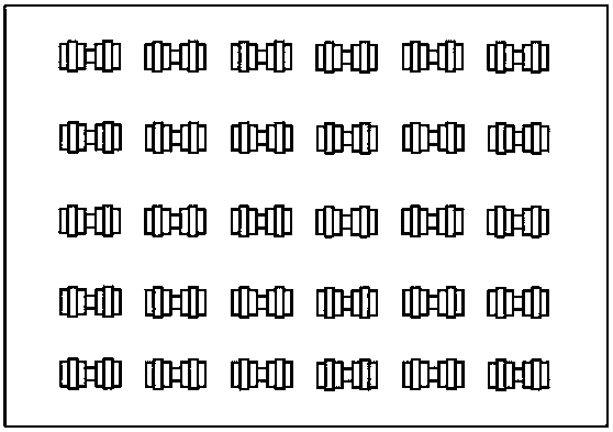
[0029] Such as figure 1 shown.

[0030] A symmetrical microwave coupling structure that connects two spaces along the Z axis. The microwave channel consists of a branch. The branch is composed of nine through holes 31 communicating along the Y direction.

[0031] The maximum length t of the microwave channel is less than 0.2 times the wavelength in free space corresponding to the central operating frequency of the microwave channel.

[0032] The cross-sectional shape of the microwave channel is an "H" shape rotated 90 degrees around the Z axis.

[0033] Along the Y direction, the maximum width of each through hole 31 increases, increases, decreases, decreases, increases, increases, decreases, decreases in sequence.

[0034] All of the through holes 31 and all of the branches are columns whose axes are along the Z direction and their lengths in the Z direction are all the same; all of the through holes 31 and all of the branches are perpendicular to the Z axis. The ends ar...

Embodiment 2

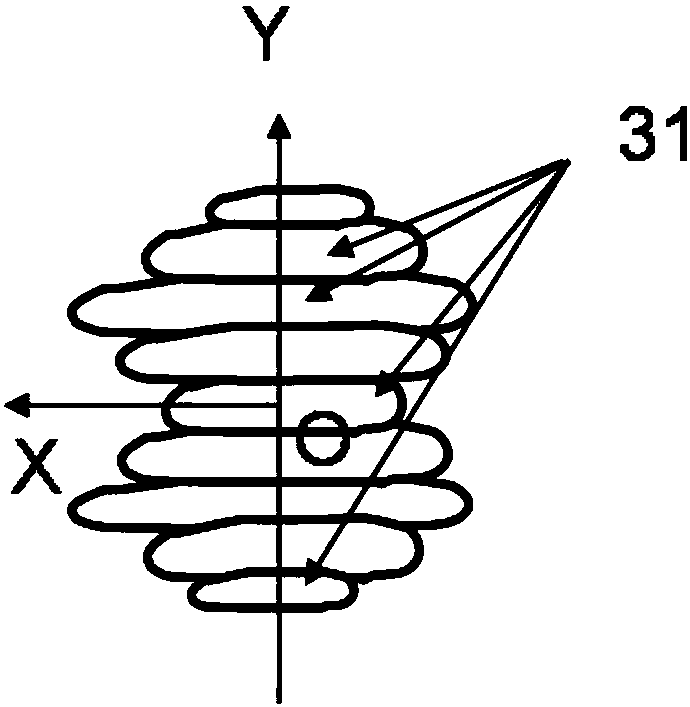
[0036] Such as figure 2 shown.

[0037] Compared with Embodiment 1, the difference of this embodiment is only that: the branch is composed of seven through holes 31 connected along the Y direction; along the Y direction, the maximum width of each through hole 31 increases, decreases, and decreases in turn. , increase, increase, decrease to form a "8" shape. All the through holes 31 have a rectangular cross-sectional shape. The rectangular through holes 31 communicate with each other through their adjacent sides in the Y direction.

Embodiment 3

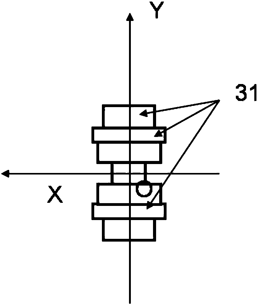
[0039] Such as image 3 shown.

[0040] Compared with implementation example 2, the difference of this implementation example is only that: the microwave channel is rotated 90 degrees around the Z axis.


PUM


Abstract

The invention discloses a symmetrical microwave coupling structure. A plurality of rectangular or through holes of other shapes are communicated with each other to form a microwave channel to be matched with various microwave circuits or to be communicated with various microwave areas. The microwave channel is in mirror symmetry. Compared with existing similar schemes, the modeling optimization calculation efficiency can be remarkably improved. The microwave circuit is smaller in size and wider in working bandwidth. Particularly, different transmission lines can be matched in an ultra-widebandfrequency range and comprise a coaxial line, a rectangular waveguide, a circular waveguide, a rectangular waveguide or a circular waveguide with a ridge, and an SIW (substrate integrated waveguide),a micro-strip, a strip line and the like. The invention can also be used for matching transmission lines having perpendicular or reversed axial lines and also used for matching different kinds of transmission lines twisting in different angles around the axial lines. The system is mainly used in communication and radar systems of microwave, millimeter wave and terahertz wave bands.

Description

technical field [0001] The invention relates to a microwave component, in particular to a compact matching coupling structure for broadband matching of various transmission lines and other microwave structures, and a microwave coupling structure for effectively connecting two spaces. Background technique [0002] In various microwave systems, the matching problem of transmission lines is common. This is because the primary function of any microwave transmission line is to transfer as much microwave energy as possible to the intended device. To achieve this, various matching circuits and mode converters are required depending on the input impedance of the target device and the operating mode. [0003] The existing matching circuits and mode converters are complex in structure, large in size and narrow in bandwidth, especially in coaxial lines and waveguide circuits. [0004] On the other hand, microwave coupling structures connecting two spaces are ubiquitous. The shape of...

Claims


Application Information

Patent Timeline
Patent Type & Authority Applications(China)
IPC IPC(8): H01P5/08
CPCH01P5/08
Inventor 王清源
Owner 成都锐烽特科技有限公司
Why Eureka
Try Eureka