Moving device for locomotive mounting

A technology of mobile devices and locomotives, which is applied in the direction of spraying devices, liquid spraying devices, and devices for coating liquid on the surface, etc. It can solve the problems of enterprise benefit reduction and production efficiency reduction, so as to increase benefits, improve production efficiency, The effect of reducing labor cost input

Pending Publication Date: 2018-09-14
重庆中铃兆虎机车制造有限公司
View PDF8 Cites 2 Cited by
  • Summary
  • Abstract
  • Description
  • Claims
  • Application Information

AI Technical Summary

Problems solved by technology

[0003] The invention provides a locomotive installation mobile device to solve the problems in the prior art that the end faces of cylindrical parts are painted manually, so that the production efficiency is seriously reduced and the enterprise benefits are reduced.

Method used


Image

  • Moving device for locomotive mounting
  • Moving device for locomotive mounting
  • Moving device for locomotive mounting

Examples


Embodiment Construction

[0027] The following is further described in detail through specific implementation methods:

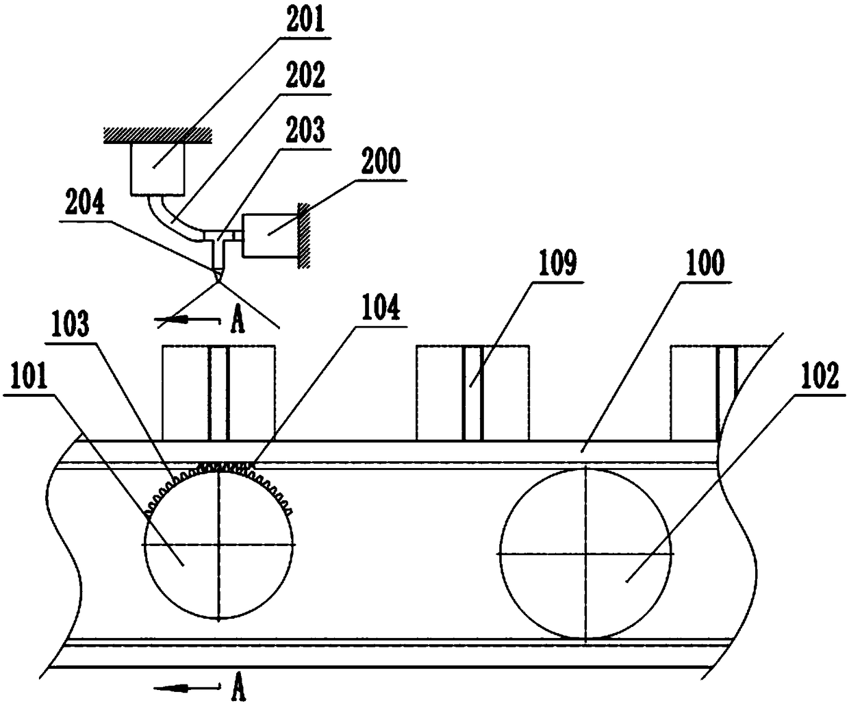
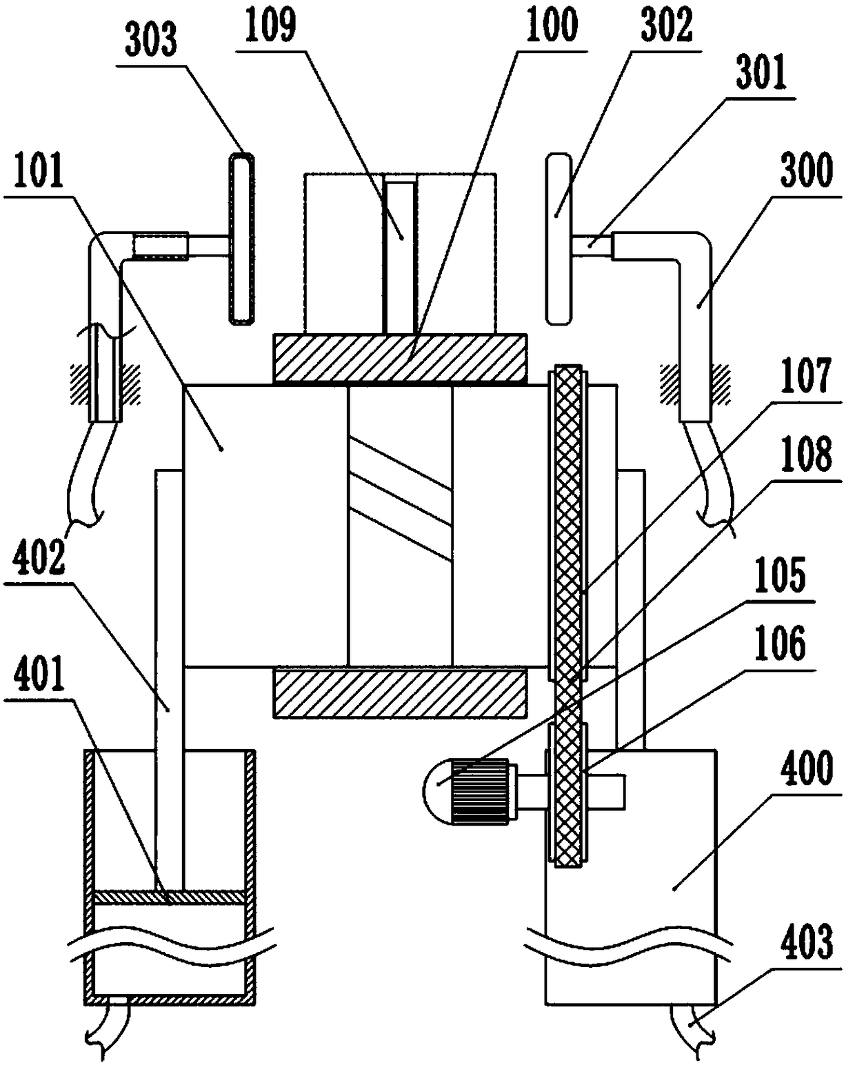
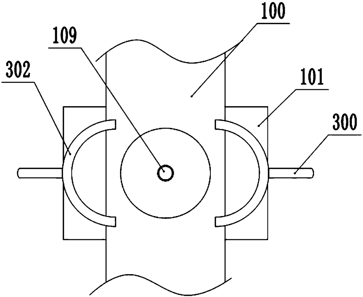
[0028] The reference signs in the accompanying drawings include: conveyor belt 100, drive shaft 101, support shaft 102, convex tooth segment 103, internal teeth 104, motor 105, driving pulley 106, driven pulley 107, belt 108, positioning rod 109 , paint can 200, air outlet pump 201, air outlet pipe 202, tee pipe 203, nozzle 204, auxiliary rod 300, support rod 301, positioning plate 302, air hole 303, cylinder 400, piston 401, piston rod 402, air supply pipe 403 .

[0029] The embodiment is basically as figure 1 and figure 2 Shown:

[0030] Locomotive-mounted mobile device, which includes a frame on which a conveying unit and a painting unit are arranged, such as figure 1 The transmission unit shown includes a conveyor belt 100, a drive shaft 101 and a plurality of support shafts 102, wherein the conveyor belt 100 is horizontally arranged and sleeved on the support shaft 102, the...


PUM


Abstract

The invention belongs to the technical field of part mounting, and specifically discloses a moving device for locomotive mounting. The moving device comprises a conveying unit and a paint spaying unit. The conveying unit comprises a conveying belt, a driving shaft and a plurality of supporting shafts. The diameter of the supporting shaft is larger than the diameter of the driving shaft. The driving shaft is provided with a driving mechanism. An inner gear is arranged on the inside wall of the conveying belt. The driving shaft is provided with a concave tooth section. The conveying belt is fixedly provided with magnetic positioning rods. An auxiliary section comprises auxiliary rods and an air-blowing mechanism. Each auxiliary rod is in a reversed-L shape and is internally hollow. Each auxiliary rod is connected with a corresponding supporting rod in a sliding mode, and each supporting rod communicates with a corresponding positioning plate. Each positioning plate is in an arc shape, and a magnetic layer is arranged on the arc surface of each positioning plate. Each magnetic layer attracts with the corresponding positioning rod when approaching the corresponding positioning rod. Theair-blowing mechanism comprises a cylinder body; a piston rod is partially hinged to the end of the driving shaft; and the cylinder body is provided with an air supply pipe. The problem that the endsurfaces of cylindrical parts are painted manually so that the production efficiency is seriously lowered and the business benefit is decreased in the prior art is solved.

Description

technical field [0001] The invention relates to the technical field of parts installation, in particular to a locomotive installation mobile device. Background technique [0002] With the continuous development and progress of the social economy, the number of locomotives in my country is gradually increasing, and the demand for locomotive parts in the locomotive aftermarket is also increasing. The factory's ability to manufacture and process locomotives is also getting stronger and stronger. At present, many parts are used in the locomotive manufacturing process, such as a cylindrical sleeve part. During the installation process, the end faces of the parts need to be painted to prevent Rust and other problems, the existing painting method is usually that the workers manually paint the end face of each part. Since this kind of sleeve parts are usually mass-produced, the amount of painting required each time is relatively large. This makes the manual method of painting not o...

Claims


Application Information

Patent Timeline
Patent Type & Authority Applications(China)
IPC IPC(8): B05B13/02B05B7/02B05D3/04
CPCB05B7/02B05B13/02B05B13/0221B05D3/0406
Inventor 陈万能
Owner 重庆中铃兆虎机车制造有限公司
Why Eureka
Try Eureka