Edge folding method of special Z-shaped workpiece

A workpiece and a special technology, applied to the integrated multi-station folding mold and its folding method and application field, can solve the problems of single use and reduction, achieve the reduction of spare parts, high bending precision, and meet the processing requirements Effect

Inactive Publication Date: 2018-09-14
ANHUI LIYUAN NUMERICAL CONTROL CUTTING TOOL & PATTERNS MFG
View PDF15 Cites 0 Cited by
  • Summary
  • Abstract
  • Description
  • Claims
  • Application Information

AI Technical Summary

Problems solved by technology

[0007] The processing of bending dies for existing special workpieces is too targeted, and the use is relatively single. It has no other use except for bending workpieces with specific shapes. If the size of the bending parts changes, the overall size of the mold needs to be changed to meet the processing requirements. Problem, the present invention provides an integrated multi-station hemming die, which is optimized on the basis of traditional bending dies, not only can complete the bending of various angles of the traditional plate, but also can complete the bending of sheet metal parts with specific shapes Processing, especially the processing of the above-mentioned special Z-shaped workpiece, its structure is relatively simple, the bending precision is high, no secondary correction is required for one-time forming, and it can adapt to the processing of bending parts of the same shape and different sizes, and the amount of spare parts is greatly reduced

Method used


Image

  • Edge folding method of special Z-shaped workpiece
  • Edge folding method of special Z-shaped workpiece
  • Edge folding method of special Z-shaped workpiece

Examples


Embodiment 1

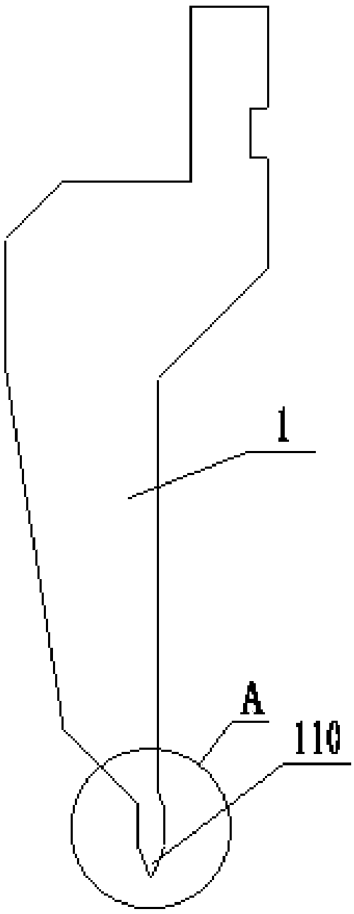
[0062] Such as figure 2 , Figure 4 , Figure 5 , Image 6 , Figure 7 with Figure 8 As shown, the integrated multi-station flanging mold of the present embodiment includes an upper mold 1, a middle mold 2 and a lower mold 3; wherein, the middle mold 2 includes a middle mold base 210 and a die 220, and the left side of the middle mold base 210 An L-shaped notch is provided on the side, and the die 220 is placed in the L-shaped notch, and is detachably connected with the middle mold base 210 by bolts. It should be noted that the middle mold base 210 and the concave mold 220 can be of an integrated structure, while this embodiment adopts a detachable connection structure, which is convenient for processing and saves materials, and is also convenient for maintenance, and will be scrapped due to wear and tear after long-term use Finally, only one of them needs to be replaced, reducing maintenance costs. The upper surface of the die 220 is provided with a V-shaped groove 22...

Embodiment 2

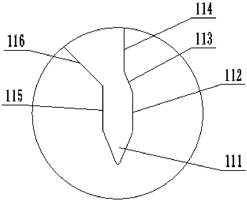
[0068] The integrated multi-station hemming die of this embodiment is further improved on the basis of Embodiment 1 to meet the bending requirements of special Z-shaped workpieces. figure 2 with image 3 , in the working part 110 of the upper mold 1, the right side of the V-shaped die head 111 is sequentially connected to the first side 112, the second side 113 and the third side 114, the first side 112 and the third side 114 are vertical planes, the second The two sides 113 are inclined planes, and the angle between the first side 112 and the second side 113 is greater than 180°; the left side of the V-shaped die head 111 is connected to the fourth side 115 and the fifth side 116 in turn, and the fourth side 115 is a vertical plane , the angle between the fourth side 115 and the fifth side 116 is greater than 90° but less than 180°. This kind of structural design can avoid the upturning of both sides during bending when bending special Z-shaped workpieces, so that the proce...

Embodiment 3

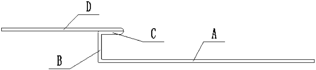
[0070] The present embodiment provides the bending method of special Z-shaped workpiece, and the special Z-shaped workpiece shape of bending is as follows figure 1 As shown, the thickness of the workpiece is 1.5mm, and it includes the first flat section A, the second flat section B, the third flat section C and the fourth flat section D connected in sequence, wherein the first flat section A and the second flat section The included angle between the flat sections B and the included angle between the second flat section B and the third flat section C are both 90°, and the included angle between the third flat section C and the fourth flat section D is 0°, That is to say, the fourth flat section D is in close contact with the third flat section C. The integrated multi-station flanging mold of embodiment 2 is adopted for processing, and the specific operation steps are as follows:

[0071] ① Mold installation preparation

[0072] According to the mechanism of embodiment 2, the ...


PUM

PropertyMeasurementUnit
thicknessaaaaaaaaaa

Abstract

The invention discloses an edge folding method of a special Z-shaped workpiece, and belongs to the field of mold design. The method comprises the following steps that firstly, a V-shaped mold head ismade contact and a plate material is bent to 90 degrees; then the plate material is overturned, and the V-shaped mold head extrudes the plate material into a V-shaped groove to form an acute angle, and a third flat section C and a fourth flat section D are obtained; then, the plate material is overturned again, the other section of the workpiece is placed on a concave mold of the V-shaped groove,and when the plate material is bent by the V-shaped mold head to the 90 degrees, a first flat section A and a second flat section B are obtained; and then the first flat section A of the workpiece istightly attached to the lower surface of a pressing plate, the second flat section B is tightly pasted to the side face of the pressing plate, the third flat section C is pasted to the upper surface of the pressing plate, the V-shaped mold head is pressed into the V-shaped groove of the concave mold and drives a middle mold base to move downwards, the middle mold base moves downwards and extrudesa fourth flat section D, the included angle between the third flat section C and the fourth flat section D is enabled to be 0 degree, so that the formed special Z-shaped workpiece is obtained. The edge folding method of the special Z-shaped workpiece can be used for machining special Z-shaped workpieces with high efficiency and high quality.

Description

[0001] This application is a divisional application of a patent application titled: Integrated multi-station hemming mold and its hemming method and application, application number: 201611212350.X, and application date: December 25, 2016. technical field [0002] The invention belongs to the field of mold design, and more specifically relates to an integrated multi-station hemming mold and a hemming method and application thereof. Background technique [0003] Since the reform and opening up, China's economic development has achieved world-renowned achievements. Its economic strength and comprehensive national strength have been greatly developed in recent decades. The economic strength continues to rise and the economic growth rate continues to accelerate. China The economy has become the focus of attention of countries all over the world. However, in recent years, with the changes in the international environment and the sharp increase in labor costs, Chinese companies are...

Claims


Application Information

Patent Timeline
Patent Type & Authority Applications(China)
IPC IPC(8): B21D11/20B21D37/10
CPCB21D11/20B21D37/10
Inventor 张迎年张一帆王克文张先进
Owner ANHUI LIYUAN NUMERICAL CONTROL CUTTING TOOL & PATTERNS MFG
Why Eureka
Try Eureka