Heat pipe automatic welding method

An automatic welding and cooling pipe technology, applied in welding equipment, auxiliary welding equipment, welding/cutting auxiliary equipment, etc., can solve the problems of lower qualified rate of radiator products, high labor intensity, low degree of automation, etc., to improve welding The effect of improving efficiency, reducing labor intensity and improving welding quality

Active Publication Date: 2020-05-12
青岛恒泰散热器有限公司
View PDF6 Cites 0 Cited by
  • Summary
  • Abstract
  • Description
  • Claims
  • Application Information

AI Technical Summary

Problems solved by technology

[0003] The existing welding method has the following defects: (1) the welding work is all completed by manpower, so the labor intensity is high, the work efficiency is low, and the degree of automation is low; (2) in the process of welding the welding head and steel pipe at both ends, due to The two ends are welded separately, so secondary positioning is required during the welding process. During the secondary positioning process, positioning errors will inevitably occur, and positioning errors will directly affect the welding quality of the chip head and steel pipe, which not only reduces the finished product of the radiator The pass rate also brings a great potential safety hazard to users

Method used


Image

  • Heat pipe automatic welding method
  • Heat pipe automatic welding method
  • Heat pipe automatic welding method

Examples


Embodiment Construction

[0032] In order to further elaborate the technical means and effects that the present invention adopts for reaching the intended invention purpose, below in conjunction with the accompanying drawings and preferred embodiments, the specific implementation, structure, features and effects of the present invention are described in detail as follows:

[0033] A heat pipe automatic welding method, comprising the following steps:

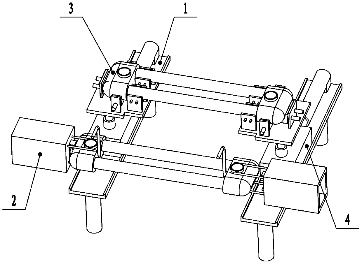
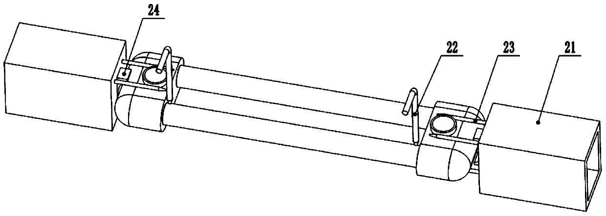
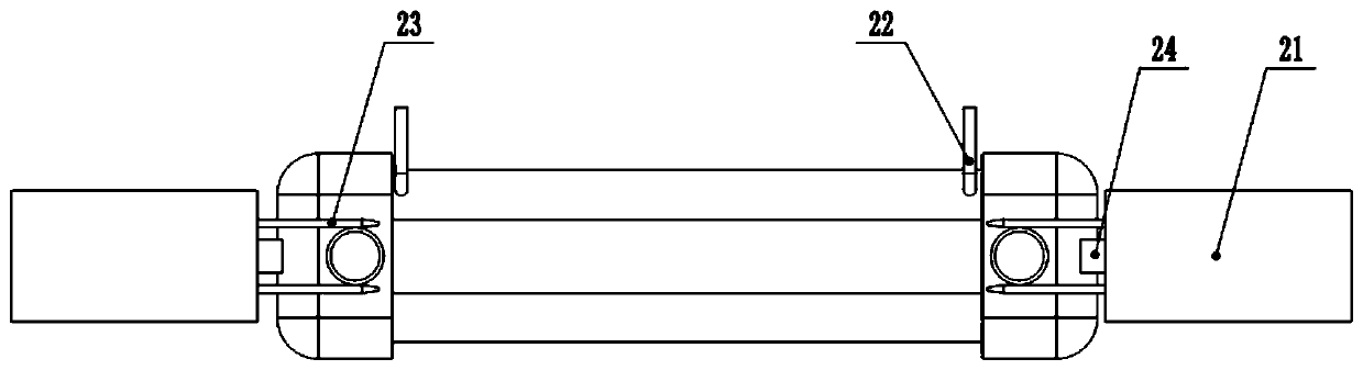
[0034] The first step is clamping and positioning. The cooling pipe includes two ends of the chip and two steel pipes between the two heads. At the feeding station, the positions of the chip and the steel pipe are respectively fixed by the feeding unit, and at the same time the chip is pressed to the direction of the steel pipe so that the chip and the steel pipe are clamped. Tight, there are weld seams at the joints of the steel pipe and the chip head respectively.

[0035] Such as Figure 7 As shown, the feeding unit 3 includes two moving plates 31, a...


PUM


Abstract

The invention relates to the field of radiator welding, in particular to a radiator pipe automatic welding method. The method comprises the steps of clamping and locating, spot welding, welding and conveying. Through the welding method, automatic welding on sheet heads and a steel pipe is achieved, and all welding operation can be completed through one-time locating; the welding efficiency of radiator pipes is improved, and the labor intensity of workers is reduced; meanwhile, the welding quality of the sheet heads and the steel pipe is improved, and the qualified rate of finished products ofradiator pipes is guaranteed.

Description

technical field [0001] The invention relates to the field of radiator welding, in particular to an automatic welding method for heat dissipation pipes. Background technique [0002] The radiator is composed of several pieces of heat pipes. During the processing of a single piece of heat pipe, the head and the steel pipe are usually processed separately, and the steel pipe is placed between the head on the left and right sides, and then the steel pipe and the head are welded together. Fixed connection. Because the shape of the chip head and the weld seam between the steel pipe is not a regular shape, the current welding method still adopts manual welding. [0003] The existing welding method has the following defects: (1) the welding work is all completed by manpower, so the labor intensity is high, the work efficiency is low, and the degree of automation is low; (2) in the process of welding the welding head and steel pipe at both ends, due to The two ends are welded separ...

Claims


Application Information

Patent Timeline
Patent Type & Authority Patents(China)
IPC IPC(8): B23K37/053
CPCB23K37/0533
Inventor 屈波
Owner 青岛恒泰散热器有限公司
Why Eureka
Try Eureka