Light guide plate full-automatic numerical control polishing apparatus

A light guide plate, fully automatic technology, applied in the direction of grinding/polishing equipment, grinding automatic control device, metal processing equipment, etc., can solve the problems of small dust collection area, affecting product quality, easy deviation of light guide plate, etc., to achieve Improve the final accuracy, improve efficiency, and save labor

Pending Publication Date: 2018-09-14
KUNSHAN HENGDA PRECISION MACHINERY IND CO LTD
View PDF1 Cites 3 Cited by
  • Summary
  • Abstract
  • Description
  • Claims
  • Application Information

AI Technical Summary

Problems solved by technology

In the polishing process of the mobile phone light guide plate, since the polishing motor is a high-speed motor with a speed of 20,000 revolutions per second, the position accuracy of the light guide plate product is required to be high. However, the positioning accuracy of the positioning device in the prior art is not ideal. Easy to shift, unable to achieve precise positioning, affecting product quality
[0004] For example, the positioning mechanism disclosed in the Chinese patent "Positioning Mechanism and Its Conveying Device and Positioning Me...

Method used


Image

  • Light guide plate full-automatic numerical control polishing apparatus
  • Light guide plate full-automatic numerical control polishing apparatus
  • Light guide plate full-automatic numerical control polishing apparatus

Examples


Embodiment

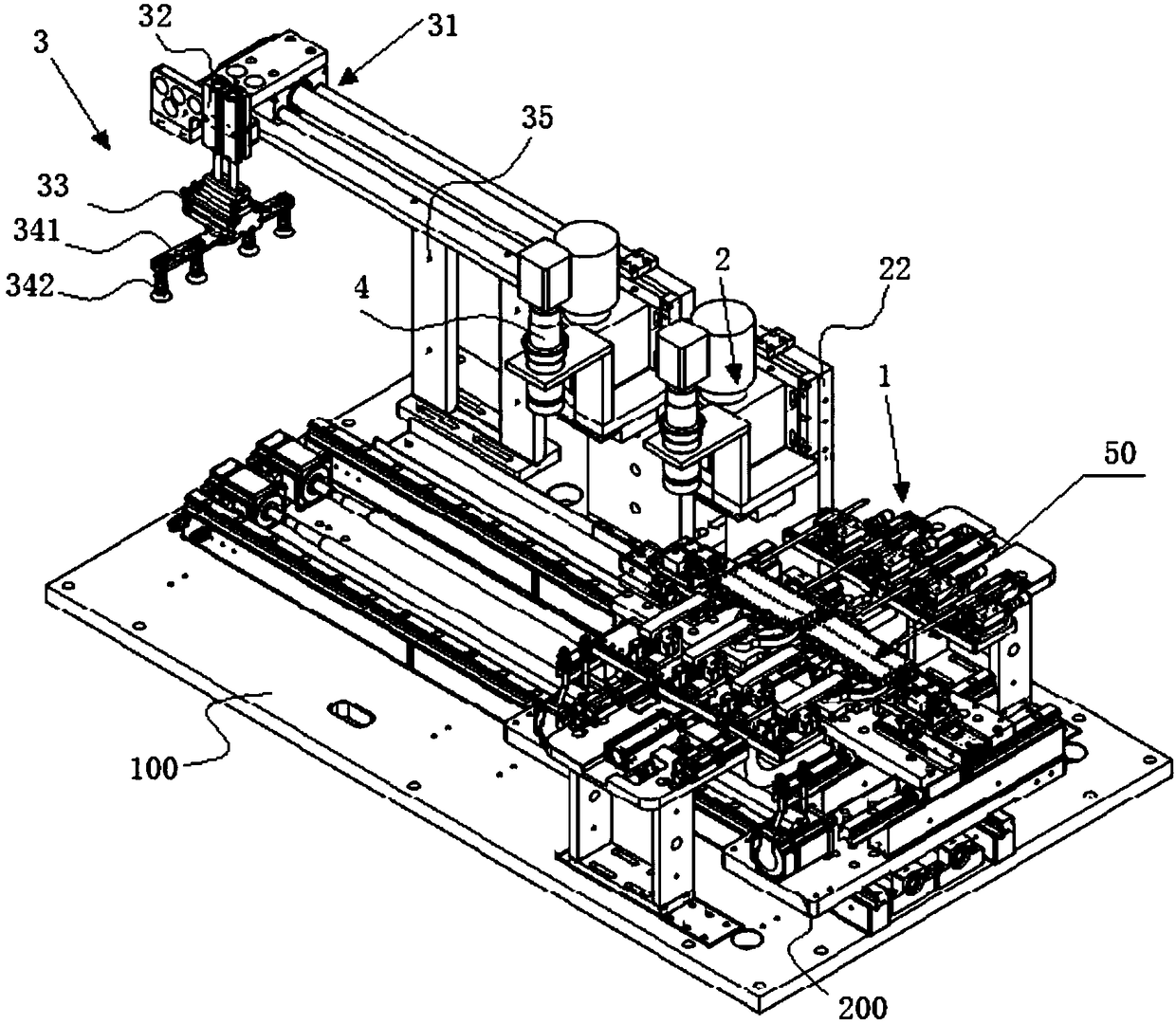
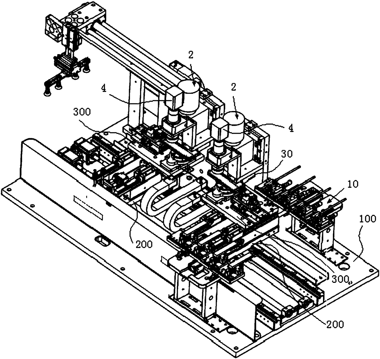
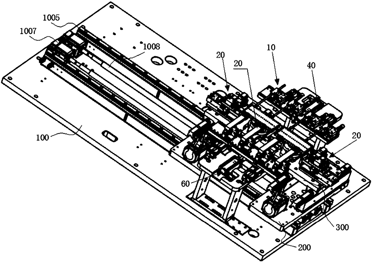
[0060] Embodiment: a kind of light guide plate automatic numerical control polishing equipment, such as Figure 1 to Figure 18 As shown, it includes a workbench and a positioning device 1 located on the workbench, a polishing device 2 and a retrieving device 3, and the retrieving device is located downstream of the polishing device; the workbench is equipped with at least one for The rotating platform 50 that fixes the light guide plate is connected with a rotating drive mechanism that drives the rotating platform to rotate horizontally, and the workbench is also equipped with an X-axis drive that can drive the rotating platform to reciprocate and translate along the X-axis direction. mechanism and a Y-axis drive mechanism capable of driving the rotating platform to reciprocate and translate along the Y-axis direction;

[0061]The polishing equipment is also provided with a control system, and the positioning device, the polishing device, the retrieving device, the rotation dr...


PUM


Abstract

The invention discloses a light guide plate full-automatic numerical control polishing apparatus. The light guide plate full-automatic numerical control polishing apparatus comprises a workbench, a positioning device, a polishing device, a material taking device and a dust collection cover. The positioning device, the polishing device, the material taking device and the dust collection cover are arranged on the workbench. The workbench is provided with at least one rotary platform for fixing a light guide plate. The rotary platform is connected with a rotation driving mechanism for driving therotary platform to rotate horizontally. The workbench is further provided with an X-axis-direction driving mechanism and a Y-axis-direction driving mechanism, wherein the X-axis-direction driving mechanism can drive the rotary platform to horizontally move in the X-axis direction back and forth, and the Y-axis-direction driving mechanism can drive the rotary platform to horizontally move in the Y-axis direction back and forth. The light guide plate full-automatic numerical control polishing apparatus is further provided with a control system. A full-automatic operation mode is adopted by thelight guide plate full-automatic numerical control polishing apparatus, all the mechanisms can automatically return, and therefore, the efficiency is improved; and additionally, by using a first positioning mechanism and a second positioning mechanism in cooperation, datum positioning is formed by the side face, positioned by adopting the first positioning mechanism or a positioning plate, of thetwo opposite side faces of the light guide plate, buffer compensation type positioning is formed by the other side face positioned by adopting the second positioning mechanism, and then, accurate positioning is achieved; and the dust collection efficiency is as high as 99.5%.

Description

technical field [0001] The invention belongs to the technical field of automation equipment, and in particular relates to an automation equipment suitable for the polishing process of a light guide plate. Background technique [0002] The working principle of the mobile phone screen light guide plate is derived from the liquid crystal display screen of the notebook computer. It is a high-tech product that transforms the line light source into a surface light source. Optical-grade acrylic (PMMA) / PC is used as the base material, and the backlight module technology of LCD display and notebook computer is used to pass through the high light transmission rate of the light guide point, and the light guide point is calculated by the computer, so that the light of the light guide plate is refracted into Manufacture and molding of surface light source in uniform light state. It has distinctive features such as ultra-thin, ultra-bright, uniform light guide, energy saving, environment...

Claims


Application Information

Patent Timeline
IPC IPC(8): B24B29/02B24B55/06B24B41/00B24B41/06B24B41/02B24B47/04B24B51/00
CPCB24B29/02B24B41/005B24B41/02B24B41/06B24B47/04B24B51/00B24B55/06
Inventor 范光得
Owner KUNSHAN HENGDA PRECISION MACHINERY IND CO LTD
Why Eureka
Try Eureka