Rear single-propeller foldable type composite wing manned aircraft with thrust-free composite auxiliary wings

A propeller and composite wing technology, applied in the field of aircraft, can solve the problems of high take-off and landing requirements, low safety factor, and low structural strength of the wing, so as to reduce the acceleration of gravity, increase the structural strength of the wing, and expand the area of ​​the wing. Effect

Inactive Publication Date: 2018-09-14
JIANGSU CHANGTAN ROBOT CO LTD
View PDF4 Cites 0 Cited by
  • Summary
  • Abstract
  • Description
  • Claims
  • Application Information

AI Technical Summary

Problems solved by technology

The traditional fixed wing has the advantages of fast flight speed, low energy consumption, etc., but it has the disadvantages that the main wing and the horizontal tail are not connected front and rear, the wing structure is not strong, easy to be damaged, the take-off and landing requirements are high, and the take-off and landing distance is long; the traditional vertical The take-off and landing aircraft has the advantages of convenient take-off and landing, but has the disadvantages of high energy consumption, low safety factor, poor load capacity, slow horizontal flight speed, and easy crash; although the current vertical take-off and landing fixed wing has the characteristics of convenient take-off and landing , but the controllability is not ideal when flying horizontally, and there are disadvantages such as large flight resistance, high energy consumption, and low safety factor.

Method used


Image

  • Rear single-propeller foldable type composite wing manned aircraft with thrust-free composite auxiliary wings
  • Rear single-propeller foldable type composite wing manned aircraft with thrust-free composite auxiliary wings
  • Rear single-propeller foldable type composite wing manned aircraft with thrust-free composite auxiliary wings

Examples


Embodiment Construction

[0034] The present invention will be further described below in conjunction with the accompanying drawings.

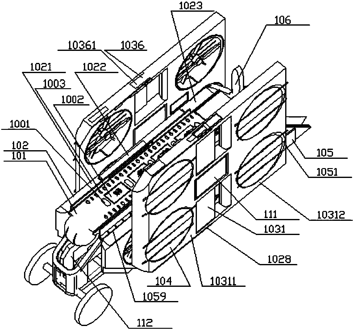
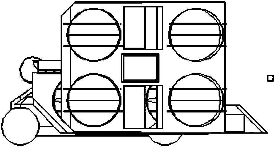
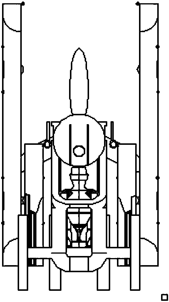
[0035] Such as Figure 1 to Figure 5 As shown, the rear single-propeller foldable compound-wing manned aircraft with no-thrust compound ailerons comprises a rear single-propeller compound-wing aircraft and non-thrust self-powered composite ailerons 1031 movably installed on both sides of the compound-lift aircraft; 111, the engine installation position; the manned compartment 112 is installed below the body.

[0036] Wherein, the rear single propeller compound wing aircraft includes a body 101, a composite lift wing 102 and a propeller 106 that can be folded and installed on both sides of the body 101; wherein, the body 101 is set as a deck platform; The lift wing 102 has a built-in self-enclosed ducted fan 104, and the composite lift wing 102 is designed with wing hinges (1028);

[0037] The non-thrust self-powered composite aileron 1031 is provided with a self-encl...


PUM


Abstract

The invention discloses a composite lift force aircraft with a development platform. The composite lift force aircraft consist of a rear single-propeller type composite wing aircraft, thrust-free self-powered composite auxiliary wings assembled at the two sides of the rear single-propeller type composite wing aircraft and an manned bin, wherein the rear single-propeller type composite wing aircraft comprises a machine body, composite lift force wings which are mounted at the two sides of the machine body in a foldable mode, and a propeller; the machine body is a deck platform; self-sealing ducted fans are arranged in the composite lift force wings; wing hinges are designed at the outer sides of the composite lift force wings; self-sealing ducted fans are arranged in the thrust-free self-powered composite auxiliary wings; an electric-liquid gas interface and a wing hinge are arranged at one side or the two sides of each propeller thrust self-powered composite auxiliary wing, and are movably connected with the composite lift force wings through the wing hinges; and the manned bin 112 is mounted below the machine body. The composite lift force aircraft has the characteristics of beingshort in takeoff and landing distance, high in flying speed, high in wing structural strength, capable of storing energy by wings, low in flying energy consumption, long in hang time, high in safetyand the like.

Description

technical field [0001] The invention relates to an aircraft, in particular to a rear single propeller foldable composite wing manned aircraft with a non-thrust composite auxiliary wing, which belongs to the technical field of aircraft equipment. Background technique [0002] Existing aircraft are mainly divided into two categories: fixed-wing and vertical take-off and landing aircraft (such as helicopters and multi-rotors). Of course, there is also a vertical take-off and landing fixed-wing product. The traditional fixed wing has the advantages of fast flight speed, low energy consumption, etc., but it has the disadvantages that the main wing and the horizontal tail are not connected front and rear, the wing structure is not strong, easy to be damaged, the take-off and landing requirements are high, and the take-off and landing distance is long; the traditional vertical The take-off and landing aircraft has the advantages of convenient take-off and landing, but has the disa...

Claims


Application Information

Patent Timeline
Patent Type & Authority Applications(China)
IPC IPC(8): B64C27/22B64C27/20B64C1/30B64C3/54
Inventor 任曲波
Owner JIANGSU CHANGTAN ROBOT CO LTD
Why Eureka
Try Eureka