
A paddle and drone

A blade and blade root technology, applied in the field of blades and UAVs, can solve the problems of reducing the efficiency of UAVs, the blades cannot be folded, and the edges of the blades are sharp, etc., so that it is easy to fold and carry out, saving paddles The effect that leaves take up space and are not easy to fly out

Active Publication Date: 2020-07-03
华南智能机器人创新研究院 +2
View PDF8 Cites 0 Cited by
  • Summary
  • Abstract
  • Description
  • Claims
  • Application Information

AI Technical Summary

Problems solved by technology

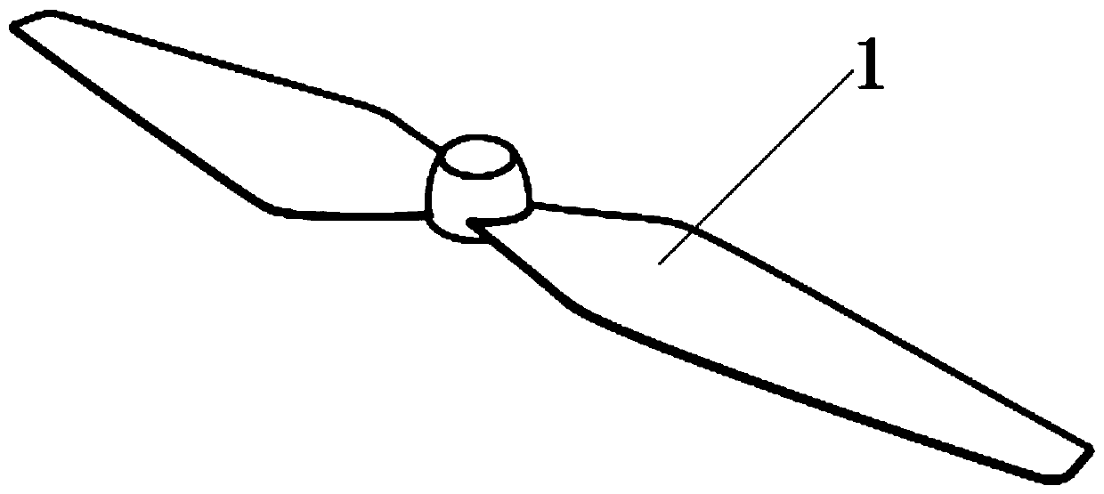
[0002] As one of the important accessories of drones, the blade is driven by a motor and cuts the air through high-speed rotation to generate lift. It is the main source of power for drones, especially rotor drones. The traditional blade structure is as follows: figure 1 As shown, the traditional blade 1 adopts an integrated fixed structure. The advantages of this type of blade are low processing cost, high overall strength, and good motion balance. However, due to the fixed structure, it takes up a lot of space and the blade cannot be folded. , the edge of the blade is sharp, which may scratch the user, and it is extremely inconvenient to carry out
UAVs using this kind of traditional blades generally adopt the method of removing the blades and installing the blades before the movement of the UAV, which reduces the use efficiency of the UAV; on the other hand, when a certain blade After the side blade is damaged, the traditional blade 1 needs to be replaced as a whole, and the maintenance cost is high

Method used


Image

  • A paddle and drone
  • A paddle and drone
  • A paddle and drone

Examples


Embodiment 1

[0051] Embodiment 1: The root and / or end of the sub-blade can be made of a magnetic substance such as a sheet magnet, so that the sub-blade is magnetic. In order to allow the sub-blade to be sucked tightly on the avoidance groove, in this embodiment, iron sheets, magnets and other paramagnetic or ferromagnetic substances that can be absorbed by the sub-blade are installed between the top surface of the propeller head and the avoidance grooves on both sides. , the embodiment of the present invention names it as a magnetic sheet or a magnetic block. When the 6 blades of the sub paddle are in the expanded state or the retracted state, they can be adsorbed on the paramagnetic or ferromagnetic substance by their own magnetism. Cling to the avoidance groove. It should be noted that, in order to avoid the phenomenon of magnetic repulsion at the same level, a magnetic attraction piece 707 and a magnetic attraction block 707 should be installed separately between the top surface of the...

Embodiment 2

[0052] Embodiment 2: The sub-blades are made of paramagnetic or ferromagnetic materials, and magnetic substances such as magnets are installed between the top surface of the paddle head and the avoidance grooves on both sides. block; when the 6 blades of the sub paddles are in the unfolded state or in the retracted state, they can be respectively adsorbed on the paramagnetic or ferromagnetic substances, and cling to the avoidance groove.

[0053] The structure of the above relevant embodiment one and embodiment two can refer to Figure 7 The schematic diagram of the cross-sectional structure of the blade is shown, in which the parts with the part numbers 707 and 708 can be magnetic sheets, magnetic blocks, magnetic sheets or magnetic blocks, and the differences are mainly reflected in their materials.

Embodiment approach

[0054] Figure 7 A schematic diagram of a cross-sectional structure of a blade according to an embodiment of the present invention is shown. Further, in order to avoid the sub-blade accidentally unfolding and keeping it in the unfolded state in a static state, causing damage, the magnet on the top surface of the sub-blade can be replaced by an energized coil. Since the propeller head is moving, the coil’s The power supply should also be designed accordingly. The specific implementation is as follows:

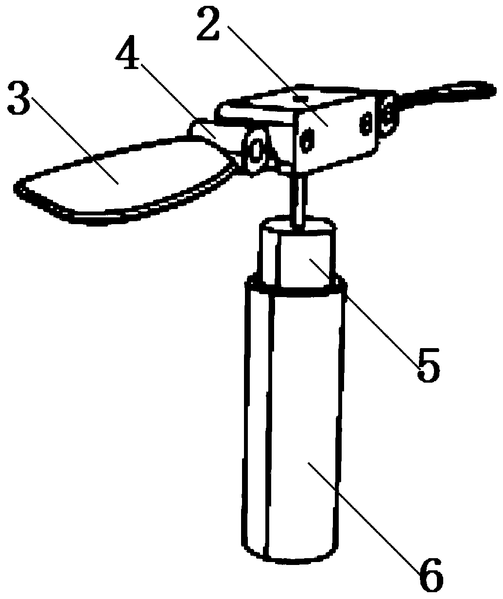
[0055] A circle of coil 701 is embedded on the top surface of the paddle head 2 , and the winding of the coil 701 is symmetrical to the center of the rotation axis of the paddle head 2 and passes above the two avoidance grooves. Both ends of the coil 701 are arranged near the rotation axis of the paddle head 2 . As can be seen from the structure introduced above, the motor shaft 501 of the driving motor 5 is fixed on the rotation axis of the propeller head 2; Cooperate to re...


PUM


Abstract

The invention provides a paddle and a drone. The paddle adopts the design of foldable sub-blades, which can save the space occupied by the paddles, facilitate the folding of the paddles and carry them out, and prevent collisions and damages. The user has a certain protective effect; the design of the self-locking thread on the propeller head facilitates the disassembly and replacement of the propeller, and the self-locking design can ensure that the propeller turns tighter and is not easy to fly out; the propeller is held based on the magnetic suction method The retracted state or unfolded state of the blade is conducive to improving the safety and stability of the blade; in the event of a collision, when a sub-blade is damaged, only the damaged sub-blade needs to be replaced, and the propeller head and the other sub-blade remain intact. It can be used continuously and the maintenance cost is low. The UAV using this blade has the characteristics of good portability, low maintenance cost, and strong stability.

Description

technical field [0001] The invention relates to the field of unmanned aerial vehicles, in particular to a blade and an unmanned aerial vehicle. Background technique [0002] As one of the important accessories of drones, the blade is driven by a motor and cuts the air through high-speed rotation to generate lift. It is the main source of power for drones, especially rotor drones. The traditional blade structure is as follows: figure 1 As shown, the traditional blade 1 adopts an integrated fixed structure. The advantages of this type of blade are low processing cost, high overall strength, and good motion balance. However, due to the fixed structure, it takes up a lot of space and the blade cannot be folded. , the edge of the blade is sharp, which may scratch the user, and it is extremely inconvenient to carry out. UAVs using this kind of traditional blades generally adopt the method of removing the blades and installing the blades before the movement of the UAV, which reduc...

Claims


Application Information

Patent Timeline
Patent Type & Authority Patents(China)
IPC IPC(8): B64C27/50
CPCB64C27/50B64U50/19B64U30/20
Inventor 陈再励曹永军钟震宇唐宇
Owner 华南智能机器人创新研究院
Learn More