Lower hanging device tube structure cavity structure of upper coverage building and application method thereof

An application method and building technology, applied in the direction of building structure, construction, etc., can solve the problems of large floor load, inconvenient access, increase construction cost, etc., to reduce the overall structural load, improve space utilization, and save construction costs. Effect

Pending Publication Date: 2018-09-14
SHANGHAI TUNNEL ENGINEERING RAILWAY TRANSPORTATION DESIGN INSTITUTE
View PDF10 Cites 0 Cited by
  • Summary
  • Abstract
  • Description
  • Claims
  • Application Information

AI Technical Summary

Problems solved by technology

At this time, the upper building and the entire equipment interlayer have a very large load on its bottom slab, and the bottom slab is located above the lower building, so it is very easy to affect the structural safety of the lower building as the service life increases. sexual influence
At the same time, due to the installation of the whole layer of equipment interlayer, the ground elevation of the first floor of the superstructure will be raised again, which not only greatly increases the construction cost, but also brings great impact on the use of the superstructure, such as people's entry and exit. inconvenient

Method used


Image

  • Lower hanging device tube structure cavity structure of upper coverage building and application method thereof
  • Lower hanging device tube structure cavity structure of upper coverage building and application method thereof
  • Lower hanging device tube structure cavity structure of upper coverage building and application method thereof

Examples


Embodiment

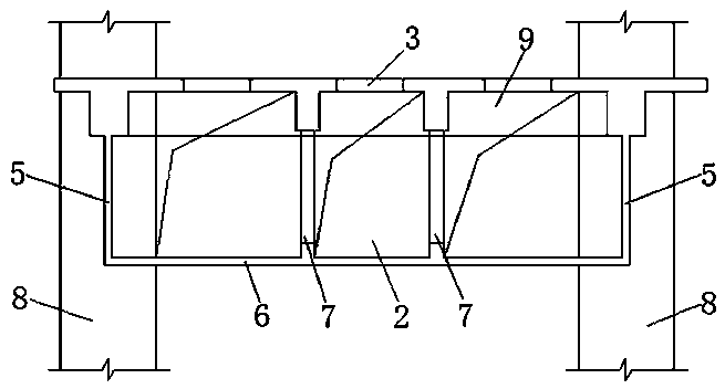
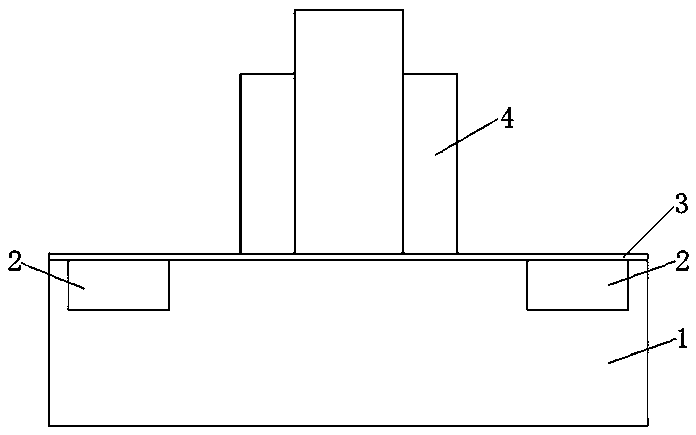
[0018] Example: as image 3 As shown, in this embodiment, the tubular cavity structure of the lower hanging equipment of the superstructure is applied to the development engineering design of the superstructure 4 . The superstructure 4 is constructed above the floor 3 . An undercover building 1 is also provided below the floor 3, and the undercover building 1 may be an urban rail transit vehicle base. like image 3 As shown, the tubular cavity 2 is suspended and fixed on the lower surface of the floor 3 for carrying the equipment pipelines of the superstructure 4 . The tubular cavity 2 is independent from the upper building 4 and the lower building 1, that is, the construction space of the tubular cavity 2 is self-contained and does not interfere with the upper building 4 and the lower building 1.

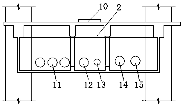
[0019] like figure 1 As shown, the tubular cavity 2 is constructed by the tubular cavity hanging wall 5 , the tubular cavity bottom plate 6 , and the tubular cavity hanging col...


PUM


Abstract

The invention relates to the technical field of upper coverage building design and construction, in particular to a lower hanging device tube structure cavity structure of an upper coverage building and an application method thereof. The lower hanging device tube structure cavity structure of the upper coverage building is characterized in that tube structure cavities are fixed to the lower surface of plate ground in a hanging mode and internal areas of cavities of the tube structure cavities are used for bearing device pipelines of the upper coverage building, and the tube structure cavities,the upper coverage building and a under-coverage building are independent. The lower hanging device tube structure cavity structure of the upper coverage building and the application method thereof have the advantages that (1), centralized layout space for the device pipelines required for the upper coverage building is provided, and the layout of the device pipelines is facilitated; (2), the upper cover development and the under-coverage building are clearly demarcated and do not interfere with each other in the vertical space and pipeline configuration, and a complete outdoor safe evacuation platform for an upper coverage building group is created; (3), operational technical support for the upper cover development is provided; (4), a sinking foundation pit for an upper development escalator and other installation equipment can be contained to improve space utilization; and (5), the whole structural load of an upper cover development building is reduced, and the construction cost issaved.

Description

technical field [0001] The invention relates to the technical field of superstructure design and construction, in particular to a tubular cavity structure of a lower hanging equipment of a superstructure and an application method thereof. Background technique [0002] At present, when developing superstructures above substructures such as urban rail transit vehicle bases, the equipment pipelines of superstructures are often arranged below the bottom of superstructures by means of a whole-layer equipment sandwich. At this time, the superstructure and the whole layer of equipment mezzanine have a very large load on its bottom plate, and the bottom plate is located above the substructure. Therefore, with the increase of service life, it is very easy to ensure the structural safety of the substructure. sex affects. At the same time, due to the installation of a whole layer of equipment interlayer, the ground level of the first floor of the superstructure will be raised again, w...

Claims


Application Information

Patent Timeline
Patent Type & Authority Applications(China)
IPC IPC(8): E04B1/00
CPCE04B1/0023
Inventor 杨雷郭劲松刘力温玉君刘辉樊玉萍李尧倪旭伟姜爱荣朱蓓玲何宏涛
Owner SHANGHAI TUNNEL ENGINEERING RAILWAY TRANSPORTATION DESIGN INSTITUTE
Why Eureka
Try Eureka