
Bidirectional sealing switching device and method and gas filter

A bidirectional sealing and switching device technology, which is applied in the field of gas filters and bidirectional sealing switching devices, can solve problems such as long maintenance and operation time, safety accidents, and complicated processing technology

Pending Publication Date: 2018-09-14
GUANGZHOU DEV GRP CO LTD +2
View PDF10 Cites 1 Cited by
  • Summary
  • Abstract
  • Description
  • Claims
  • Application Information

AI Technical Summary

Problems solved by technology

[0003] At present, the traditional pressure vessel seals are mostly connected to the cylinder body by bolt fastening, which has defects such as difficult disassembly, long maintenance and operation time, and heavy equipment, which brings a lot of inconvenience to production and maintenance.
At the same time, it is necessary to process the water lines on the sealing flange, which leads to complex processing technology, difficulty in controlling the processing accuracy, and easy to wear and tear during production and operation, and there is a certain hidden danger of leakage
[0004] In terms of sealing principle, the traditional flange plate bolt fastening pressure vessel relies on the bolt connection to compress the lip-shaped sealing gasket for sealing. However, when there is a misoperation of opening under pressure during production and operation, safety accidents are prone to occur, resulting in human and financial losses.

Method used


Image

  • Bidirectional sealing switching device and method and gas filter
  • Bidirectional sealing switching device and method and gas filter
  • Bidirectional sealing switching device and method and gas filter

Examples


Embodiment Construction

[0035] In order to facilitate the understanding of the present invention, the present invention will be described more fully below with reference to the associated drawings. Preferred embodiments of the invention are shown in the accompanying drawings. However, the present invention can be embodied in many different forms and is not limited to the embodiments described herein. On the contrary, the purpose of providing these embodiments is to make the disclosure of the present invention more thorough and comprehensive.

[0036] It should be noted that when an element is referred to as being “fixed” to another element, it can be directly on the other element or there can also be an intervening element. When an element is referred to as being "connected to" another element, it can be directly connected to the other element or intervening elements may also be present. The terms "vertical," "horizontal," "left," "right," and similar expressions are used herein for purposes of ill...


PUM


Abstract

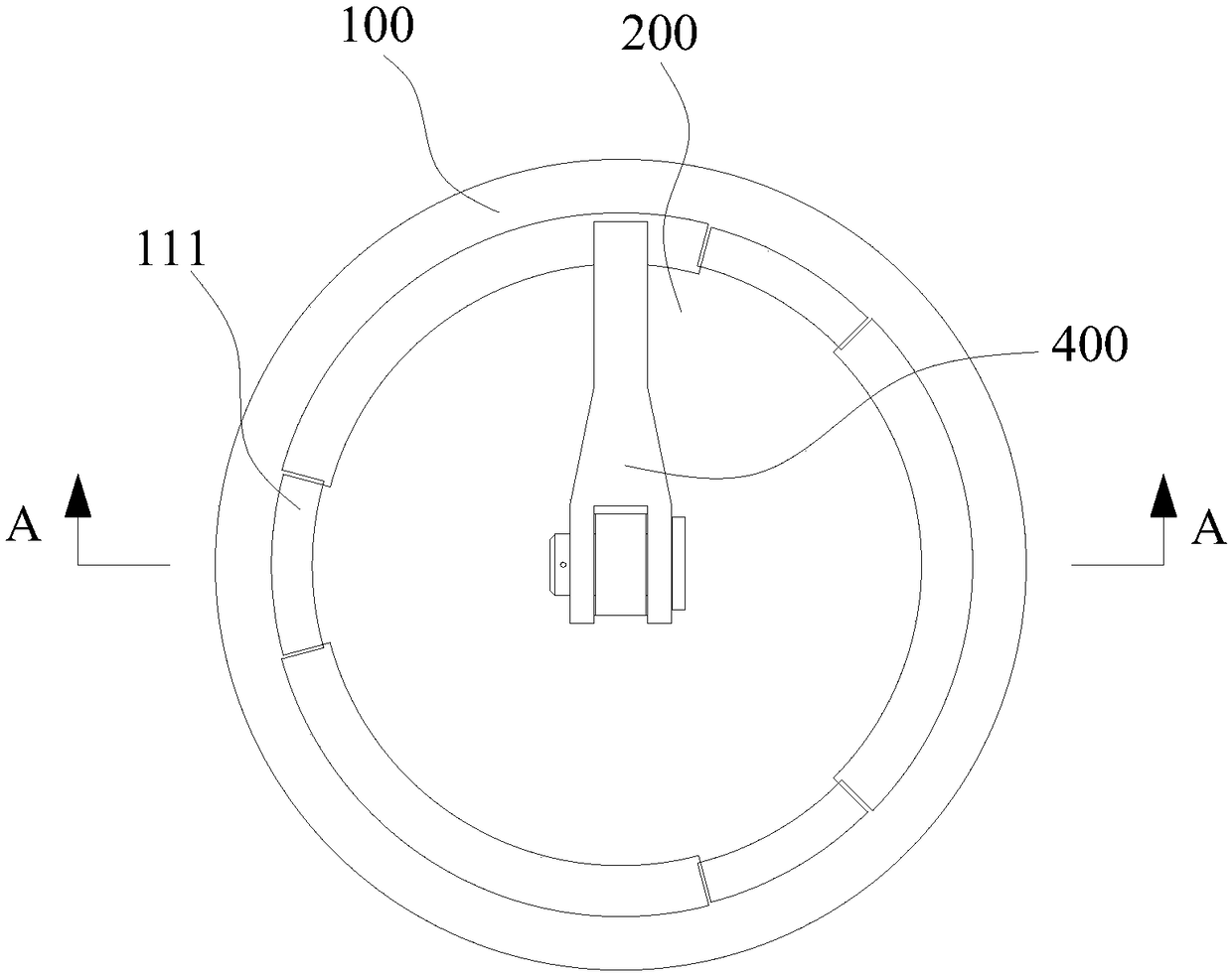
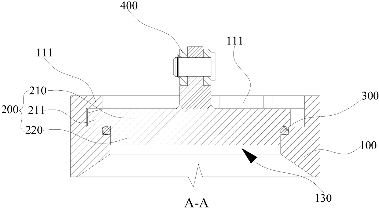
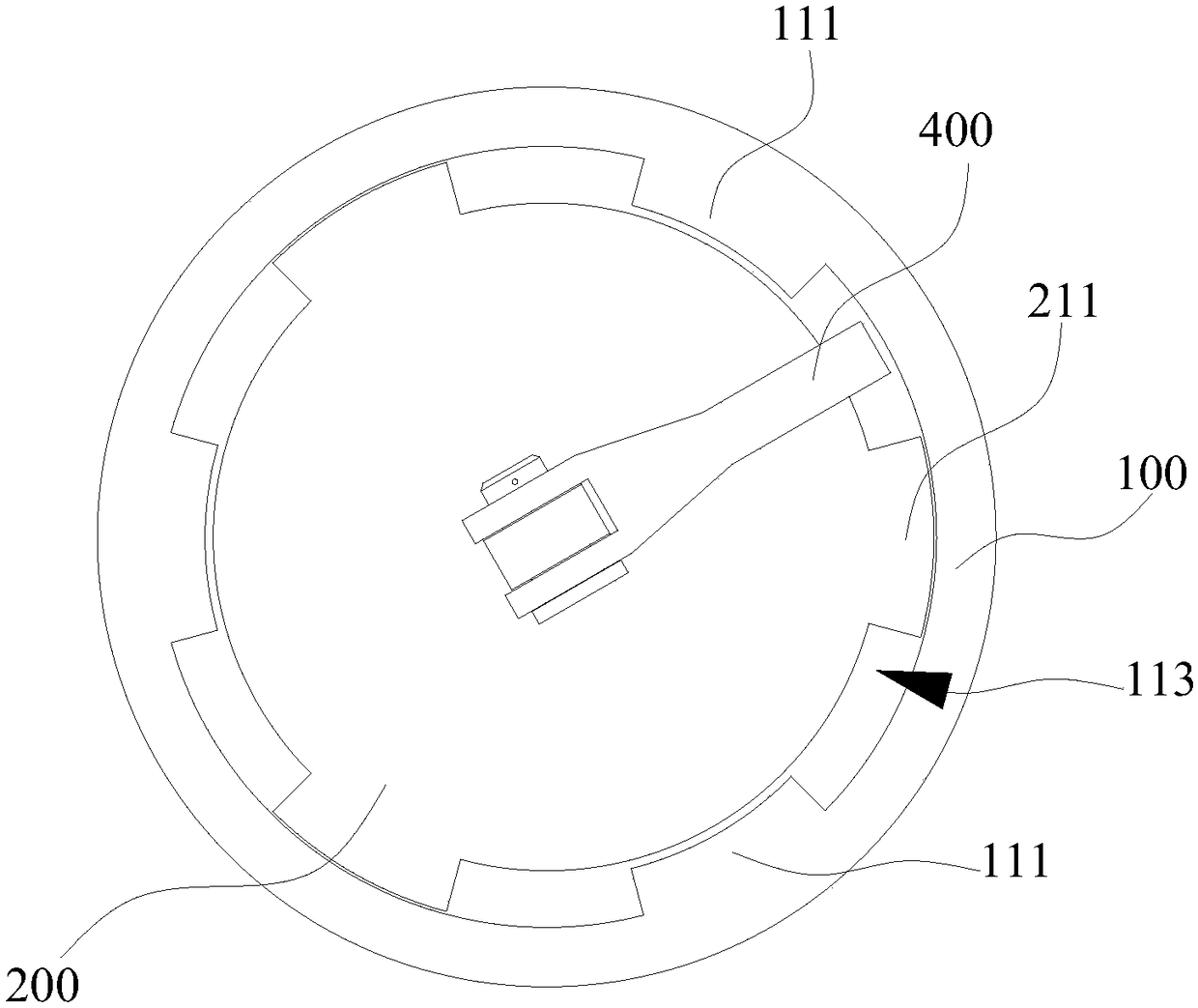
The invention discloses a bidirectional sealing switching device and method and a gas filter. The bidirectional sealing switching device comprises a barrel, a cover and a sealing ring, wherein the cover comprises a fixed cover and a bulge part arranged on one side of the fixed part; the sealing ring is arranged outside the bulge part in a sleeving manner; an inner hole of the barrel comprises a first hole section, a second hole section and a third hole section which are arranged in sequence and matched with the fixed cover, the sealing ring and the bulge part respectively; at least two first clamp teeth are arranged on the inner wall of the first hole section at intervals in the circumferential direction; second clamp teeth corresponding to the first clamp teeth are arranged on the outer edge of the fixed cover; when the second clamp teeth are located in clamp space, the upper side surface and the lower side surface of the sealing ring are propped against the inner walls of the fixed cover and the barrel respectively, and the outer side surface of the sealing ring is propped against the inner wall of the second hole section. According to the structure, with increase of pressure inthe barrel, self-locking effect and self-reinforced sealing effect can be realized, and leakage or misoperation is prevented.

Description

technical field [0001] The invention relates to the technical field of pressure vessel structures, in particular to a bidirectional sealing switch device, a method and a gas filter. Background technique [0002] Pressure vessels are widely used in industrial production processes. Taking the gas filter as an example, it is a kind of pressure vessel, which is used for gas supply at high pressure (0.4Mpa<P<4.0Mpa), medium pressure (0.01Mpa≤P≤0.4Mpa), and low pressure (P<0.01Mpa). It is widely used in the system to purify gas, protect pipelines and equipment, improve combustion quality, and improve energy efficiency. It is an indispensable filter equipment in the production of gas transmission and distribution. [0003] At present, the traditional pressure vessel seals are mostly connected to the cylinder body by bolt fastening, which has defects such as difficult disassembly, long maintenance operation time, and heavy equipment, which brings a lot of inconvenience to...

Claims


Application Information

Patent Timeline
IPC IPC(8): F16J13/22F16J13/24B01D46/00
CPCB01D46/0002B01D46/0004F16J13/22F16J13/24
Inventor 许俊城李毅陈晓明郑皓文卫国
Owner GUANGZHOU DEV GRP CO LTD
Learn More