Composite butterfly check valve
A kind of check valve and butterfly technology, applied in the field of compound butterfly check valve, which can solve the problems of imperfect valve structure and other problems
- Summary
- Abstract
- Description
- Claims
- Application Information
AI Technical Summary
Problems solved by technology
Method used
Image
Examples
Embodiment 1
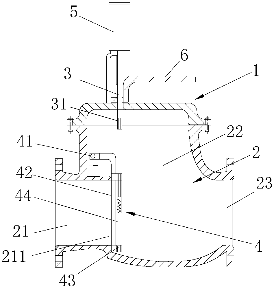
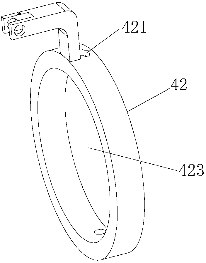
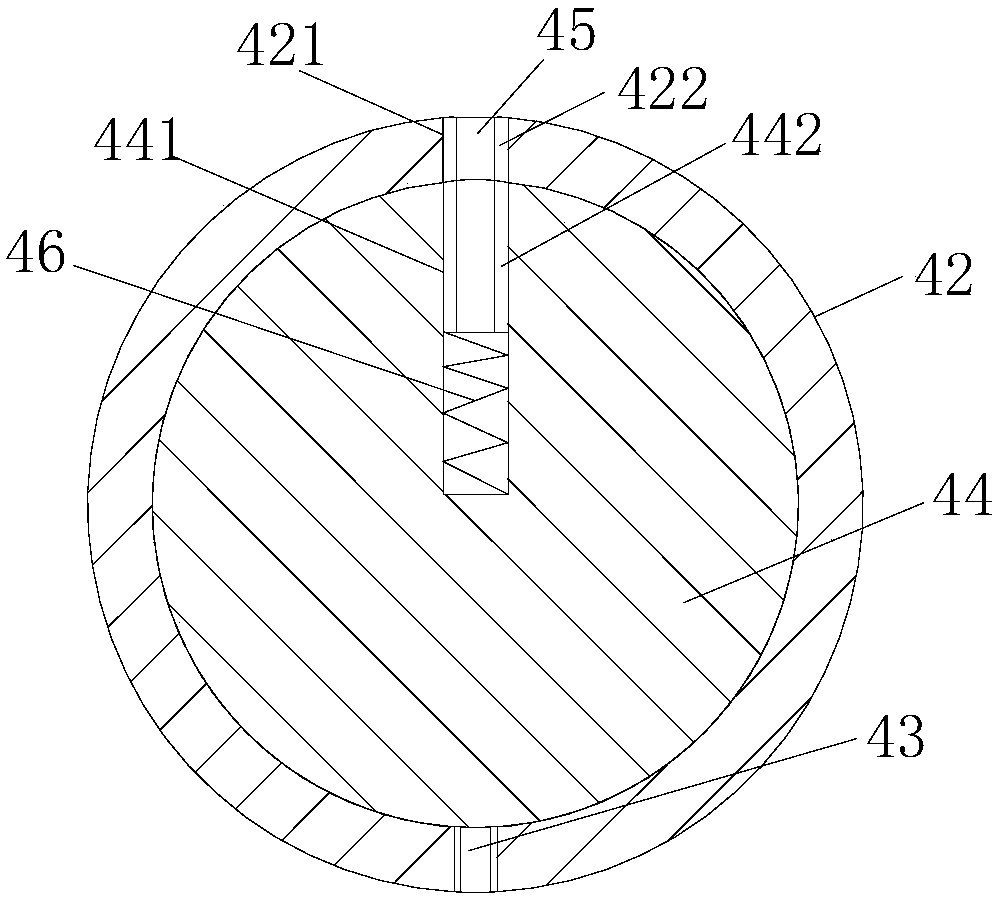
[0031] Embodiment one: if Figure 1-8As shown, this embodiment includes a valve body 1 provided with a fluid channel 2 and a valve stem 3 with one end located in the valve body 1. The fluid channel 2 includes an inlet channel 21, a valve core channel 22 and an outlet channel 23. The valve core Inside the flow channel 22 is installed a spool assembly 4 that cooperates with the valve stem 3 and is used to close or open the inlet channel. The valve core assembly 4 includes a check plate 42 connected to the valve core flow channel 22 through a first rotating shaft hinge 41 and used to close or open the inlet. The check plate 42 is provided with areas on both sides of the check plate 42 for communication. The valve hole 423 of the valve hole 423 is provided with a vertically installed second rotating shaft 43 at the bottom of the valve hole 423, and the second rotating shaft 43 and the valve hole 423 are on the same plane. Here, the fact that the valve hole 423 communicates with t...
Embodiment 2
[0036] Embodiment 2: The only difference from Embodiment 1 is that the opening of the through hole 421 is equipped with an anti-off block for preventing the limit shaft 45 from coming out of the through hole 421. The setting of the anti-off block here will not hinder The entry and exit of the driving end 31 of the valve rod 3 . The specific solution is to control the size of the valve stem 3, so that the valve stem 3 avoids the position of the anti-off stopper, so that the valve stem 3 can freely enter and exit the through hole 421, and when the valve stem 3 rotates, the valve stem 3 can avoid Open the anti-off block, and do not interfere with each other. Wherein, in addition to being arranged at the opening of the through hole 421, the anti-off block can also be arranged at the middle or lower part of the through hole 421, as long as it can prevent the limit shaft 45 from entering without interfering with the limit shaft 45 and get final product. In this embodiment, since th...
Embodiment 3
[0037] Embodiment 3: The difference from Embodiment 1 is that a first magnetic piece is provided at the driving end 31 of the valve stem 3, and a second magnetic piece is provided at the end of the limit shaft 45 opposite to the driving end 31 of the valve stem 3, The magnetic force between the first magnetic part and the second magnetic part repels each other. The wall of the through hole 421 is provided with a third magnetic piece that is magnetically attracted to the second magnetic piece, and the second magnetic piece is attracted by the third magnetic piece, which reduces the possibility of the limiting shaft 45 coming out of the through hole.
[0038] In the present invention, if figure 1 The second rotation axis shown is in the vertical direction. The vertical here does not only refer to the angle of view shown in the figure. If the valve as a whole deflects, the second rotation axis can also deflect, and the valve stem, blind hole, through hole It only needs to be con...
PUM
 Abstract
Description
Claims
Application Information
 - R&D
- Intellectual Property
- Life Sciences
- Materials
- Tech Scout
- Unparalleled Data Quality
- Higher Quality Content
- 60% Fewer Hallucinations
Browse by: Latest US Patents, China's latest patents, Technical Efficacy Thesaurus, Application Domain, Technology Topic, Popular Technical Reports.
© 2025 PatSnap. All rights reserved.Legal|Privacy policy|Modern Slavery Act Transparency Statement|Sitemap|About US| Contact US: help@patsnap.com


