Method for locating buried gas pipeline leakage point based on tracer gas

A gas pipeline and tracer gas technology, which is applied in pipeline systems, gas/liquid distribution and storage, mechanical equipment, etc., can solve the problems of inaccurate positioning, loss, complex surrounding environment, etc., to avoid waste of resources and short detection period , the effect is obvious

Active Publication Date: 2018-09-14
BEIJING GAS GRP
View PDF9 Cites 12 Cited by
  • Summary
  • Abstract
  • Description
  • Claims
  • Application Information

AI Technical Summary

Problems solved by technology

[0002] With the continuous expansion of city size and population increase, the demand for gas is also increasing, the scale of natural gas pipelines is also expanding, and the urban buried pipeline network is becoming more and more dense. Corrosion or man-made damage and other factors lead to leakage accidents from time to time, and urban natural gas pipelines are mainly laid in densely populated areas, and the surrounding environment is relatively complex. Once leakage, fire, explosion and other accidents occur, serious casualties and property losses will be caused
[0003] The current detection and positioning of pipeline gas leakage points mainly have the problem of inaccurate positioning. The conventional detection method is mainly manual inspection. This method uses specific instruments to detect the concentration of flammabl...

Method used


Image

  • Method for locating buried gas pipeline leakage point based on tracer gas
  • Method for locating buried gas pipeline leakage point based on tracer gas
  • Method for locating buried gas pipeline leakage point based on tracer gas

Examples


Embodiment Construction

[0019] Hereinafter, exemplary embodiments of the present disclosure will be described in more detail with reference to the accompanying drawings. Although the drawings show exemplary embodiments of the present disclosure, it should be understood that the present disclosure may be implemented in various forms and should not be limited by the embodiments set forth herein. On the contrary, these embodiments are provided to enable a more thorough understanding of the present disclosure and to fully convey the scope of the present disclosure to those skilled in the art.

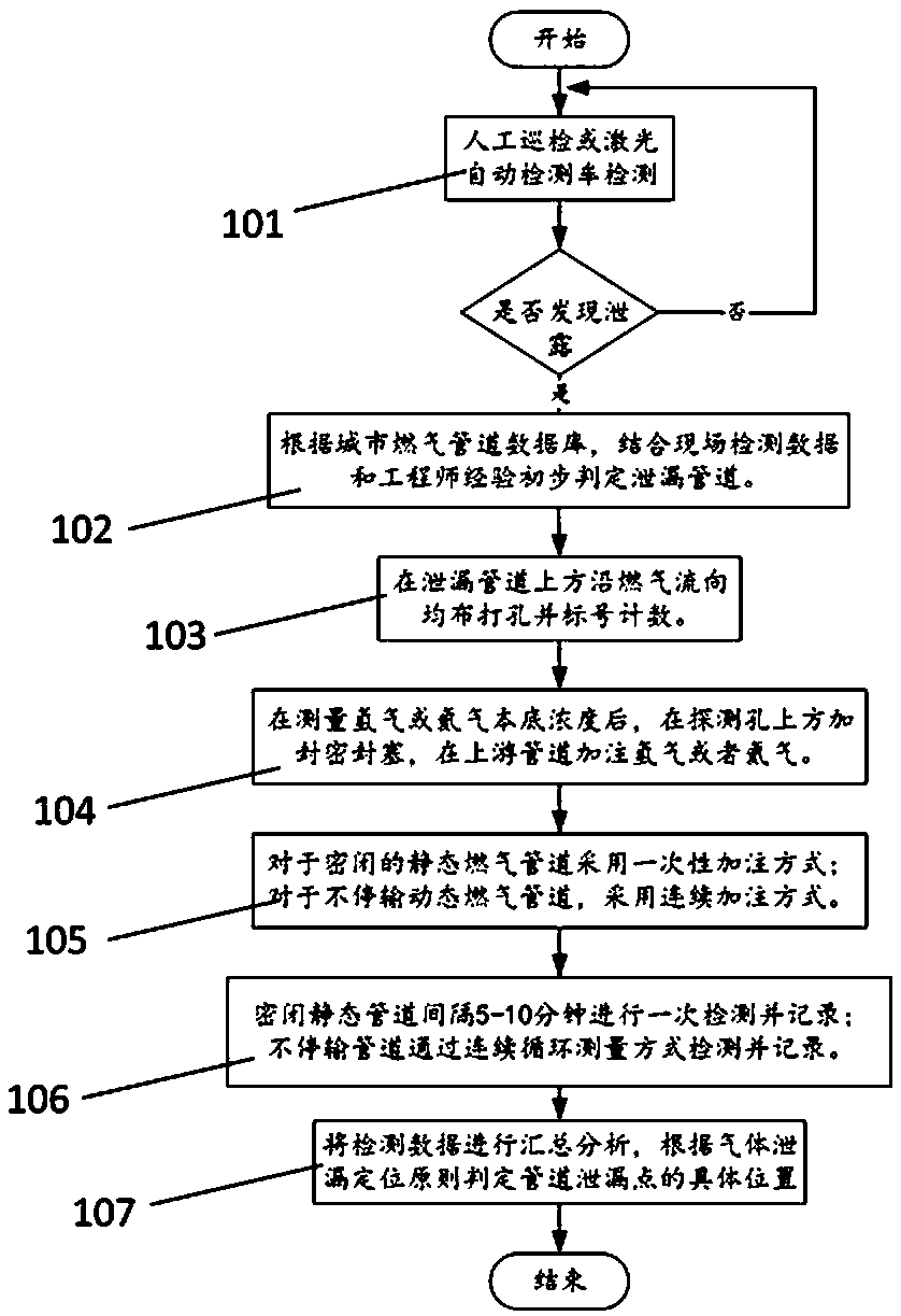
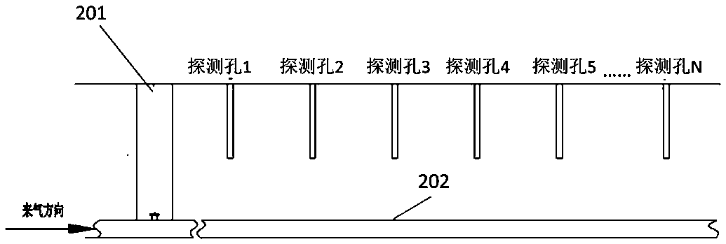
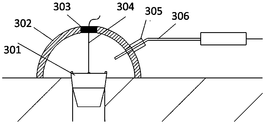
[0020] figure 1 It is a flowchart of a method for locating a leak point of a buried gas pipeline based on tracer gas according to an embodiment of the present invention. figure 2 It is a schematic diagram of the arrangement of detection holes along the pipeline according to an embodiment of the present invention. image 3 It is a schematic diagram of the detection process of the tracer gas detector according to an em...


PUM


Abstract

The invention provides a method for locating a buried gas pipeline leakage point based on tracer gas. The method comprises the steps that whether leakage exists in a gas pipeline or not is detected, and if the leakage exists in the gas pipeline, the following operations are carried out, that is, the location of the leakage pipeline is determined, holes are drilled in the determined leakage pipeline in the direction of gas flow, probe holes are labeled and counted, and the background concentration of H2 or He in the pipeline is measured; for a closed static gas pipeline, the following operations are carried out, that is, H2 or He tracer gas is injected into the closed static gas pipeline at a time, and tracer gas concentration is detected and recorded at predetermined intervals; and for a dynamic gas pipeline which does not stop conveying, the following operations are carried out, that is, the H2 or He tracer gas is injected into the dynamic gas pipeline continuously, the tracer gas concentration is continuously detected and recorded, and the location of the leakage point of the pipeline is determined based on the tracer gas concentration recorded in the closed static gas pipeline or the tracer gas concentration recorded in the dynamic gas pipeline.

Description

Technical field [0001] The invention relates to the technical field of urban gas pipeline equipment detection, in particular to a method for locating leak points of buried gas pipelines based on tracer gas. Background technique [0002] With the continuous expansion of the scale of cities and the increase of population, the demand for gas is also increasing, and the scale of natural gas pipelines is also expanding. Urban buried pipeline networks are becoming denser and denser, and pipelines are inevitable due to natural aging during operation. Corrosion or man-made damage causes leakage accidents from time to time. Urban natural gas pipelines are mainly laid in densely populated areas and the surrounding environment is more complicated. Once leakage, fire, explosion and other accidents occur, it will cause serious casualties and property losses. [0003] The current detection and positioning of pipeline gas leak points mainly suffer from inaccurate positioning. The conventional det...

Claims


Application Information

Patent Timeline
IPC IPC(8): F17D5/02
CPCF17D5/02
Inventor 李胜国韩赞东马旭卿刘瑶黄丽丽邢琳琳王建
Owner BEIJING GAS GRP
Why Eureka
Try Eureka