
Heating equipment

A technology of heating equipment and heating chamber, which is applied in the direction of lighting and heating equipment, electric furnace heating, furnace control device, etc., which can solve the problems of environmental pollution, safety and hidden dangers, and achieve the effect of simple equipment structure, convenient operation and high degree of intelligence

Inactive Publication Date: 2018-09-14
何正和
View PDF5 Cites 1 Cited by
  • Summary
  • Abstract
  • Description
  • Claims
  • Application Information

AI Technical Summary

Problems solved by technology

[0002] In the processing and production of some refractory materials, some heating equipment is often used to heat the refractory material to test the refractory performance. Traditional heating equipment generally uses open flames generated by gas combustion, which not only pollutes the environment but also has certain safety. Hidden danger, this device effectively solves this problem

Method used


Image

  • Heating equipment
  • Heating equipment
  • Heating equipment

Examples


Embodiment Construction

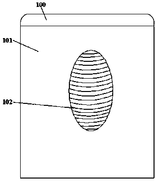
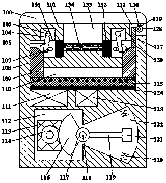
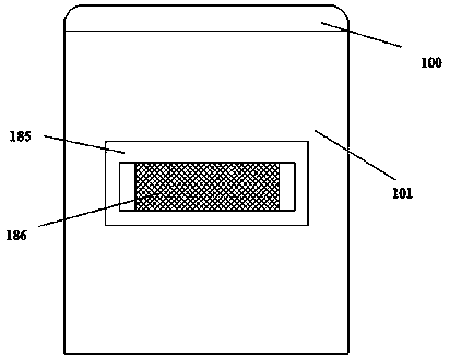
[0017] Such as Figure 1-Figure 3 As shown, a heating device of the present invention includes a box body 101 and a cover plate 100 arranged on the top of the box body 101, and the left and right sides of the box body 101 are provided with carrying slots 185 at the same time, and the carrying slots 185 is provided with a handle 186, and the top end surface of the box body 101 is provided with a concave groove 131 with a notch upward, and the right end of the concave groove 131 runs through the right end surface of the box body 101, and the concave groove 131 The rotation fit is connected with the first revolving pin shaft 128, the first revolving pin shaft 128 is provided with the first toothed wheel 129, the top of the first toothed wheel 129 is provided with a strut 130, and the top of the strut 130 is The end surface is fixedly connected with the bottom end surface of the cover plate 100, and a heating cavity 133 with a notch upward is provided in the box body 101, and a sy...


PUM


Abstract

The invention discloses heating equipment which comprises a tank body and a cover plate arranged on the top of the tank body; a recessed groove with an upward notch is formed in the end surface of thetop of the tank body; the right end of the recessed groove penetrates through the end surface of the right end of the tank body; a first rotary pin shaft is rotationally matched with and connected tothe interior of the recessed groove and is provided with a first toothed wheel; a supporting rod is arranged on the top of the first toothed wheel; the end surface of the top of the supporting rod isfixedly connected with the end surface of the bottom of the cover plate; the tank body is internally provided with a heating cavity with an upward notch; symmetric first cavity bodies are formed in the left inner wall and the right inner wall of the heating cavity in a communicating manner; a second cavity body with a downward notch is arranged on the top of each first cavity body in the communicating manner; a first slipping groove is formed in the bottom of the heating cavity; a second slipping groove is formed between each first cavity body and the first slipping groove in the communicating manner; and a third cavity body is formed at the bottom of the first slipping groove.

Description

technical field [0001] The invention relates to the technical field of heating equipment, in particular to a heating equipment. Background technique [0002] In the processing and production of some refractory materials, some heating equipment is often used to heat the refractory material to test the refractory performance. Traditional heating equipment generally uses open flames generated by gas combustion, which not only pollutes the environment but also has certain safety. Hidden danger, this device effectively solves this problem. Contents of the invention [0003] The technical problem to be solved by the present invention is to provide a heating device, which can solve the above-mentioned problems in the prior art. [0004] The present invention is achieved through the following technical solutions: a heating device of the present invention includes a box body and a cover plate arranged on the top of the box body, and the left and right sides of the box body are pro...

Claims


Application Information

Patent Timeline
IPC IPC(8): F27B17/00F27D19/00F27D11/02F27D1/18H02J7/32
CPCF27B17/0016F27D1/1808F27D11/02F27D19/00F27D2001/1825H02J7/32
Inventor 何正和
Owner 何正和
Learn More